Other technical advances
All sections of this page are still in development.
This website is concerned with cement kilns, which are the unique technology of the cement industry. However, the development of some other technologies have had a significant effect upon the development of the industry. Among these, the following will be considered:
The cement industry is sufficiently old that, at its inception, all these technologies were at a pre-industrial stage of development, and the rate of their modernisation and up-take influenced the general development of the industry.
Product transportation
Perhaps the most significant technological determinant of the industry’s early geographical distribution was the transportation of the product to its market, rather than the availability of raw materials as is the modern case. Even the early cements, which were relatively high value, niche products, constituted “heavy goods”. In the pre-railway age, water was the sole mode of transport for such goods. Every producing site needed a wharf on sea, river or canal, and the only viable markets were those that could be reached by these means. Even when railways developed, as they did concurrently with the cement industry, their freight rates remained high compared with water transport. Of 113 plants listed in 1895, 51 had water transport only, 20 had rail only, and 42 had both. The majority of those with both had originally water transport only. The preponderance of coastal plants gave the British industry an edge in the early cement export market. It is significant that, because of the convenient form and high density of cement packed in casks, cement was shipped to America and other distant markets as ballast – i.e. at zero cost – and this helped stave off the development of indigenous industries in these areas. A typical example of a major plant of the early period is Vectis, which by modern standards was extremely obscurely located in the Isle of Wight, but which up to the end of the nineteenth century was a major world-wide exporter. The early plants often had large fleets of barges and ships. The raw materials for Roman cement were of an essentially coastal nature, so its manufacturers used coastal shipping to move raw materials as well as product, and this practice continued when they converted to Portland manufacture. Some major companies were involved in shipping before entering cement manufacture – e.g. Trechmann, Earle and Goldsmith. In the Medway, large barge contractors grew up to supply the widely-sought alluvial clay, and developed into cement transporters for the plants in the area.
Numbers of plants in the Midlands depended for their success on access to the London market via the narrow boats running on the Grand Union Canal. Among early plants, a fair number were initially canal-based:
| Atlas | Linley | Rugby |
| Deepfields | Llandaff Yard | Southam |
| Ellesmere Port | Newbold | Stockton |
| Harbury | Oldbury | Wakefield |
| Harefield | Rialto | Windmill |
| Kirtlington | Ringsend |
Southam delivered cement to Birmingham by barge as late as 1969, and Thames plants of Blue Circle fed their central London terminal at Hurlingham by barge until 1995.
In the Thames, Medway and East Anglian coast, the mainstay for transport was the sailing barge of typically 45 tons, and these remained in use into the 1930s. Along the east coast, the traditional Tyne colliers had a symbiotic relationship with the industry, supplying cheap coal to the Thames, and taking chalk ballast on the return trip to the cement plants of the North-east.
During the twentieth century, the importance of water transport diminished. The increasing size of the industry rendered the slow and small-scale coastal and canal barges inefficient. The fleet of small Tyne colliers was largely wiped out during WWI. At the same time, road transport developed and many new plants during the 20th century were designed with no other form of transport. By contrast with 1895, in 1995, of 23 listed plants, 4 had road transport only, 16 had road and rail, and 3 had road, rail and water, although only one of the latter – Northfleet – was set up for serious water-borne export.
Power supply
Portland cement and its predecessor Roman Cement both needed power for grinding operations. As with other developments in the Industrial Revolution, there was a tendency for industry to locate itself where cheap "natural" power was available. Parker’s Roman Cement plant at Northfleet (which became Robins) ground its materials using a windmill and an ancient tidal mill. However, the power requirement for Portland cement was greater, because of the need for raw material grinding, and because clinker is relatively hard, and when William Aspdin took over Parker's plant, he almost immediately installed steam engines for extra power. The amount of power needed to drive the moving parts of a cement plant increased rapidly up to about 1970, when a gradual downward trend began. The first plants to make Portland cement probably used less than one twentieth of the motive energy per tonne of product compared to a late 20th century plant. This was not so much due to lack of energy – which was cheap and freely available – but the lack of heavy-duty equipment that could use it. An early plant would have a wash-mill to make the slurry, and flat stones to grind the clinker, both producing only a coarse grind and tiny output, but using little power. Typically a small steam engine would run both, using a system of lay-shafts and belts. All other operations would use human power or horses. As the number of drives required increased, more steam power was provided, and by the end of the 19th century plants often had several different power plants.
The steam engines used tended to lag behind the available technology, because fuel was cheap and simple, familiar designs were favoured. Small, single expansion engines with old-fashioned Cornish and Lancashire boilers were still common on old plants in the 20th century. Newer, larger plants tended to invest in more efficient double- and triple-expansion engines with tube boilers, and from the 1890s, gas engines became favoured for new plants. The latter were usually supplied by suction producer plants. Their higher operating temperature allowed higher thermodynamic efficiency, and energy-work conversion, which was typically less than 5% for old-fashioned steam engines, could reach 15-20% with a gas engine.
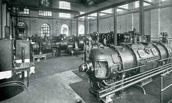 Power plant at Wilmington, around 1920. The nearby Stoneferry plant was also supplied from here. Shown are three 1.5 MW turbo-generators, two by Siemens and one by Brush Ljungstrom. The boiler house was adjacent to the left.
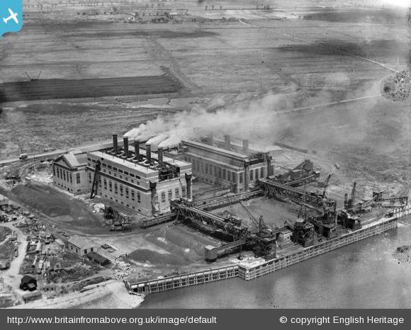 Picture: ©Historic England - NMR Aerofilms Collection. Britain from Above reference number EPW032828.
Britain from Above features some of the oldest and most valuable images of the Aerofilms Collection, a unique and important archive of aerial photographs. You can download images, share memories, and add information. 95,000 images taken between 1919 and 1953 are be available online. Barking A Power Station of the London Power Company commissioned 1925. It had a capacity of 240 MW, of which the Thames and Medway cement industry took about one third. Barking remained Britain's largest generating site through the 20s, 30s and 40s. View in High Definition.
The typical cement grinding plant direct-driven by steam or gas engine was a maze of shafts, belts and pulleys, with multiple plant items driven by each engine. The equipment had to be clustered around the engine-house, preventing a more logical linear layout of the plant. Starting and stopping of individual items was achieved either by clutches in the drive shaft, or, more usually, "fast-and-loose" pulleys. These consisted of two identically-sized pulleys side-by-side on the shaft, the "fast" pulley being keyed onto the shaft, while the "loose" pulley was free to rotate about it. To stop a piece of equipment, the drive belt was flipped from the fast pulley onto the loose pulley. These arrangements were complicated, unreliable and inefficient, and cement plants were obvious candidates for electrification, with one motor, remotely controlled, for each item of plant. A further advantage of electrification was, notwithstanding the hazardous nature of early electrical installations, an enormous improvement in operational safety. A large proportion of the frequent fatalities in the nineteenth century cement industry consisted of workers dismembered by exposed shafts and belts.
From the 1890s, some power was used to generate electricity. Electricity was initially used only for lighting - arc-lights were well suited to outdoor applications. For example, Bevans installed its first generator - a 25 kW dynamo - to light its quarry washmills and wharf in 1898. The arrival of rotary kilns corresponded more or less with the development of reliable electric motors, and although some rotary kilns were turned by steam power for many years, electrification of motive power in many cases began with the rotary kilns: the first appears to have been at Shoreham in 1900. During the first decade of the 20th century, about half the rotary kiln installations used direct steam or gas engine power via lay-shafts, although most were subsequently fitted with electric motors.
| date | plant | supplier | electric |
|---|---|---|---|
| 1901 | Shoreham | FLS | √ |
| 1901 | Swanscombe | FZ | √ |
| 1901 | Wouldham | FZ | √ |
| 1901 | Martin Earles | own | √ |
| 1902 | Newhaven | FLS | √ |
| 1903 | Arlesey | FZ | √ |
| 1903 | Stoneferry | Pol | × |
| 1904 | Bevans | FZ | √ |
| 1904 | Billingham | FZ | × |
| 1904 | Norman | FZ | × |
| 1904 | Warren | FZ | × |
| 1905 | West Kent | FZ | × |
| 1905 | Sundon | FLS | √ |
| 1905 | Beddington | Pol | √ |
| 1906 | Kirtlington | Newell | × |
| 1906 | Wilmington | Pol | × |
| 1907 | Johnsons | FLS | √ |
| 1907 | Crosfields | Pol | √ |
| 1907 | Jarrow | Newell | × |
| 1907 | Mitcheldean | Newell | × |
| 1908 | Southam | FZ | × |
| 1908 | Premier | FLS | × |
| 1909 | Harefield | FLS | √ |
| 1909 | Harbury | Krupp | × |
The electricity was initially always produced on site, typically using steam or gas engines to drive the generators, but later, much more efficient (30%+) turbo-generators were used. Bevans installed a small turbo-generator as early as 1899, but the first serious installations designed to run the whole plant were at Wouldham in 1910 and at West Thurrock and Ellesmere Port in 1912. At some locations on-site generators remained a feature (if only for back-up) for many years, the last probably being those at Rhoose, which still ran in the 1970s.
However, it is usually much more economic to use purchased power, and by the 1930s the majority of plants were taking power from local power stations: the first appears to have been Billingham, well placed in an industrial area, as early as 1907. The next seems to have been Ellesmere Port in 1921. Local grids began operation in 1933, and the National Grid began in 1938. Before 1933, purchased power required installation of a spur line from the nearest power station. In many instances, the surrounding rural locality was simultaneously provided with electricity for the first time. During the 1930s, most of the Thames and Medway industry was supplied by the Barking power station of the London Power Company.
Probably the last off-grid power house was that installed at Southam in 1937. In more recent times, only the more remote plants are provided with back-up generators, although kilns are always provided with a basic back-up drive in the event of power failure, usually consisting of a diesel engine, so that the kiln can be rotated slowly, minimising the risk of distorting the shell or damaging the refractories. Uniquely, the Quinn plants at Derrylin and Ballyconnell, although provided with grid power, are more or less self sufficient in power from their own 54 MW (peak) windfarm on Slieve Rushen. From 2014, Ketton installed a 12.5 MW solar PV array in a worked-out quarry area, subsequently expanded. Because cement plants have many such large areas of sterile land, other possible installations are being investigated.
Modern integrated plants might use 100-120 kWh per tonne of cement production, so a million tonne per year plant might draw up to 22 MW. This means that cement plants are relatively large power customers in areas that are often otherwise rural. In common with other major power users, cement companies can negotiate favourable electricity prices by managing their consumption in ways that are convenient to the power supplier. The main broad strategies employed are:
- Cheap Night-time Power. In the British context, domestic electricity demand is highest in the winter, and during the daytime. On the other hand demand for cement is lowest in the winter, so the manufacturer can fit in with the needs of the grid by concentrating its production into the night hours. This benefits the power supplier by evening out demand, but means some surplus capacity has to be maintained on the cement plant.
- Maximum Demand Management. This consists of an undertaking to avoid large peaks in demand which might put a strain on the grid, the monthly electricity bill being based not on the total monthly consumption, but on the peak day's consumption. It therefore pays the manufacturer to maintain a very constant day-to-day consumption, and erratic demand is punished with a high bill.
- Load Shedding. This consists of an undertaking to shut down most or all of the plant for a few hours at short notice, so that if the power supplier has a breakdown or maintenance shutdown, the demand can be lowered without power cuts. The supplier must call one such event in every annual billing period, even if no emergency occurs. The reward to the cement manufacturer is proportional to the amount of load shed when this is called for. Generally speaking, the plant attempts to cut all power except that to the kilns.
Quarrying
 Picture: Norman collection: "Milling" chalk marl at the Saxon quarry, around 1904. Tram-cars conveyed the marl to the drier. Careful work on the face kept the size of chalk to <50 mm, so that no crusher was necessary.
The getting of raw materials consisted of pick-and-shovel work from the start, and persisted well into the 20th century. In the chalk areas, “milling” of chalk was almost universal. Men with picks (or, later, jack-hammers) in bosun’s chairs suspended from above cut funnel shaped slots in the face, the falling chalk being diverted into a tram-car at the neck of the funnel. This had the advantage that the chalk produced was small and required no crushing prior to wash-milling, but was obviously fantastically labour-intensive.
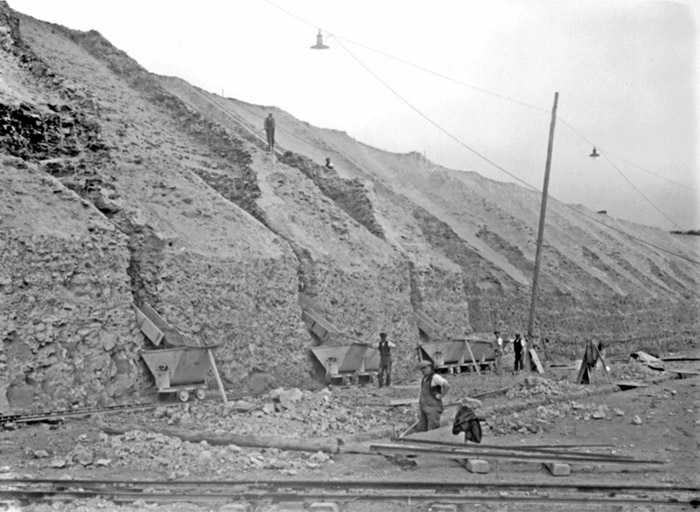
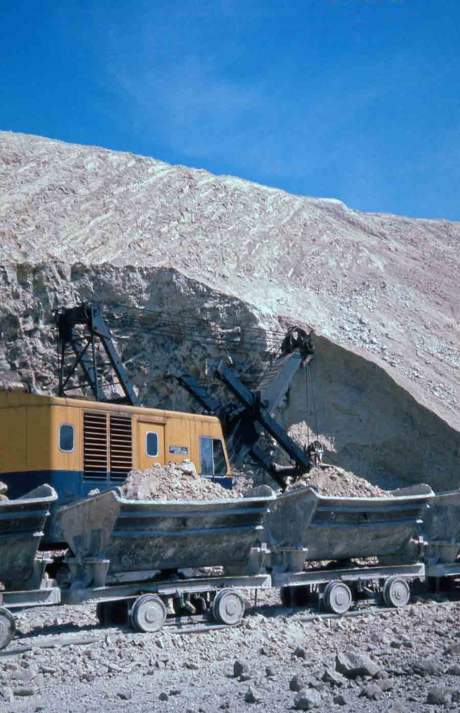
 Digging Upper Chalk at the Hessle quarry supplying Wilmington, around 1920. Tram-cars conveyed the chalk to the crushers, and it was then moved to the plant by main-line rail. Subsequent enlargement of face-shovels allowed faces over 30 m high to be worked, although face-height was ultimately limited by the weakness of the top edge of the curved surface, and faces were kept to 25 m or so.
The use of face-shovels began in the 1900s, but there were still large Thames-side plants using manual methods in the 1920s. Percy Taylor in 1947 recalled that an excavator with a three-ton bucket, when operating, did the work of about 100 men quarrying by hand. In Lias areas, hand-getting was also the norm: slabs of limestone were prised out with crow-bars and broken with hammers. This had the advantage that the best raw material could be literally hand-picked: subsequent use of mechanical means usually degraded this process, and necessitated the importation of high-grade corrective rock.
 Picture: ©Ian Capper 2008, and licensed for reuse under this Creative Commons Licence. See this and related images on Geograph. A Ruston-Bucyrus 110RB electric face shovel and the last quarry railway, at Barrington in 1982.
Steam or electric face shovels were standard for all chalk and limestone up to WWII. In the 1950s, more effective methods were developed for chalk quarrying, in the form of elevating scrapers, or for harder material, bulldozers fitted with rippers. However, face shovels continued in use at some locations - e.g. Northfleet - where high faces were to be worked in soft material. Only at - I think - Pitstone, multi-bucket face-shovels were employed, these being suitable for uniform and nearly horizontally bedded soft raw materials.
While face-shovels were used for working faces above the quarry floor, pits below the floor were worked by draglines. A classic case of quarry operation with two draglines and a face shovel is provided by Sundon - the lowest-cost plant for most of the period 1910-1970.
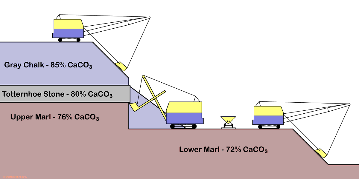 Sundon quarry operation. The upper dragline removes the top part of the Gray Chalk and drops it onto the bench below. The face shovel digs the lower part of the face, and loads the train with this and the top material thrown down. The bench level is adjusted so that the face shovel is placed at the optimum level to prise out the hard band of Totternhoe Stone. The lower dragline adds lower carbonate marl to the train. The chemistry of the mixture is controlled by varying the number of grabs of lower marl per train-load. As the thickness of the gray chalk increases, so the depth of the lower pit automatically increases to compensate. All surface water drains away into a sump in the lower pit. This system of advance automatically adjusts itself to the geology of the deposit without technical supervision. The quarry was operated by three excavator drivers and two locomotive drivers.
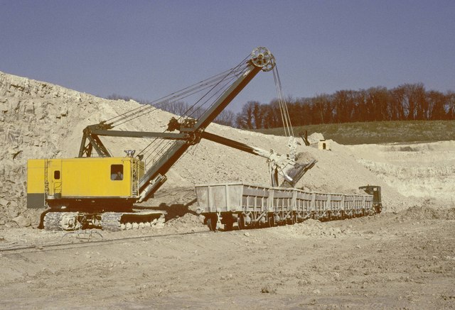
 Picture: ©Dylan Moore 2008, and licensed for reuse under this Creative Commons Licence. See this and related images on Geograph. A Ruston-Bucyrus 54RB diesel face shovel loads a train at Sundon in 1974.
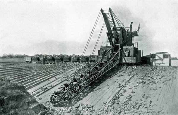 Very early (1913) multi-bucket excavator extracting alluvial clay at the Barrow on Humber clayfield supplying Wilmington. The machine discharges into tram-cars which are then hauled to the washmills on the quay. The clay was moved to the plant by barge in slurry form. Later forms of MBE discharged directly onto belt conveyors.
Where soft materials are also very wet, or even submerged, the early mechanisation consisted of draglines placed on a dry bench above, which scooped the material from a sloping surface below. Where there were well-behaved horizontal strata, a logical development was the use of a multi-bucket excavator (MBE), the largest forms of which could reach down a slope of 30 m or more. This became quite commonly employed for clay extraction, although the largest installation was on chalk marl at Rochester.
In hard rock areas, operation became indistinguishable from that of any hard-rock quarry, making subtle use of blasting to produce a maximum amount of ready-crushed material, and using normal (but big!) hydraulic front-loaders to load dump trucks. Rail (or occasionally boat) remained the sole method of transport of raw material for a long time. Long conveyor belts were not possible because of the lack of suitable rubber until after WWII; instead a less satisfactory expedient was the rope-way, which was used at some locations from the early 1900s. Dump-trucks only became common after 1950. A standard gauge quarry railway was installed as recently as 1964 at Barrington (replacing previous narrow gauge) and continued in use until 2005.
In a few rare instances, raw materials were obtained by underground mining. These included:
These have all become extinct since the closure of the anhydrite mines in the 1970s.
Size Reduction and Grinding
The techniques of crushing rock and reducing hard minerals to a powder are not unique to the cement industry, and are covered elsewhere. However, particularly with regard to the energy consumption of the industry, the key innovations in size reduction need to be tracked, and this is covered in a separate page.
Material handling
The cement making process consists of a number of processes (see Cement Plant Layout) and material has to be physically moved from one manufacturing stage to the next. Particularly in large plants with tall silos, this may involve lifting material and can potentially use considerable energy.
Gravity. If the relief of the plant site is suitable, allowing material to flow downhill under gravity is the ideal method. In practice, however, few British plant sites have any significant fall, and movement by gravity has been confined to a few quarries that were in hills above the adjacent plant site, such as Hope and Shoreham. Perhaps the most prominent was Weardale where materials were quarried and ground to rawmix in the quarry high above the Wear valley. The rawmix was then transferred to the plant on a 670 m belt conveyor, falling 90 m. The motor usually functioned only as a brake.
Manual Methods. The typical early plant moved most of its material in lump form, by means of human energy, using wheelbarrows or rail-mounted skips pushed by hand. So chalk and clay would be wheeled to the washmill, settled slurry would be wheeled to the drying flats, dried material would be wheeled to the kilns, and the clinker would finally be wheeled to the crushers and finish mill. As plants grew in size, these operations were often replaced with locomotive-pulled trains, still requiring manual loading and unloading of the trucks.
Bucket Elevators. The movement of cement to storage bins at early plants was usually automated using the ancient technology of the flour mill, since the cement was powdery. The most straightforward technique was to raise the material vertically to sufficient height that it could then slide down a chute into the bin.
Screws
Belt Conveyors developed in the USA, as vulcanised multilayer belting with abrasion resistance was developed, and became available in the UK from around 1900.
Ropeways. A number of plants used ropeways for moving materials before the development of long belt conveyors from the 1880s onwards. These included:
| Plant | material | date | loading | discharge | length | ||
|---|---|---|---|---|---|---|---|
| moved | x | y | x | y | m | ||
| Newhaven | clay | 1885 | 546909 | 109749 | 545955 | 108704 | 1415 |
| Lyme Regis | limestone | 1905 | 333142 | 91315 | 333510 | 91590 | 459 |
| Lees | clay | 1907 | 569025 | 162033 | 569557 | 163445 | 1509 |
| Harefield | clay | 1909 | 505161 | 189730 | 504903 | 189720 | 258 |
| Mitcheldean | limestone | 1909 | 365733 | 218603 | 365877 | 218386 | 260 |
| Coltness | granulated slag | 1910 | 282292 | 655600 | 282498 | 655414 | 293 |
| Ellesmere Port | clinker | 1912 | 340961 | 376658 | 340991 | 376679 | 37 |
| Cliffe | cement/coal | 1914 | 572072 | 175603 | 570714 | 176433 | 1592 |
| Humber | cement | 1925 | 496589 | 425722 | 496302 | 424597 | 1161 |
| Billingham | sulfate plant mud | 1927 | 446974 | 521796 | 448260 | 522238 | 1609 |
| Billingham | anhydrite | 1928 | 447721 | 522786 | 447281 | 522478 | 759 |
| Swanscombe | coal | 1929 | 559962 | 175937 | 560249 | 175116 | 908 |
| Billingham | clinker | 1931 | 448052 | 522628 | 448201 | 522240 | 440 |
| Dunstable | chalk | 1936 | 501431 | 223477 | 501573 | 223465 | 146 |
| Rodmell | cement | 1936 | 543539 | 106539 | 543273 | 106673 | 298 |
| Drogheda | limestone/shale | 1938 | 707635 | 776434 | 711066 | 776063 | 3580 |
| Harbury | waste shale | 1938 | 439373 | 258581 | 439089 | 258122 | 540 |
| Holborough | clay | 1938 | 569113 | 161896 | 569962 | 162696 | 1217 |
| Hope | ? | 1938 | 415956 | 382323 | 416506 | 382243 | 588 |
| South Ferriby | chalk | 1938 | 499061 | 420461 | 497287 | 420904 | 1828 |
| Aberthaw | waste shale | 1939 | 303382 | 167529 | 303994 | 167250 | 688 |
 3-throw pump - partial sectional diagram.
Pumps for liquids became central to the development of wet processing of raw materials. Early handling of slurry used gravity for transfer of slurry from the washmill (where it was produced) to the slurry back (where it was dried out). Very thin slurry was made, and it ran down flumes, usually constructed of wood. The invention of the "thick slurry" process made this less viable, and pumps started to be used. With the introduction of the chamber kiln, requiring the precise distribution of slurry over wide areas of drying chamber, usually at high level, pumps became essential. The earliest commonly-used pump (almost universal until the 1950s) was the three-throw plunger pump.
A robust design is required that can cope with gritty slurry, and so plungers are used rather than pistons. In order to maintain a constant flow-rate, multiple cylinders are required (and this should be an odd number) and in practice, three were always used. The flow-rate of slurry delivered is further smoothed out by an air-dome capacitance on the outlet manifold. The pump was capable of delivering very high pressures (up to 2 MPa), and the valve-box inspection doors were made burstable to prevent bursting of the pipe line by over-pressure.
The three-throw pump was already old technology when it began to be used in the 1870s, and evolved little over the following century. Most equipment suppliers had their own versions, all closely similar. The earliest designs typically had 8 inch (203 mm) diameter plungers, and a 16 inch (406 mm) stroke. Scale-up consisted in using wider plungers - up to 12 inches, but stroke stayed at 16 inches, since this already required about 3.5 metres headroom. Large installations simply used multiple pumps - as many as ten being used.
This page remains in development.