The following is a transcript of an anonymous article that describes the plant as originally constructed. It appeared in Cement and Cement Manufacture, VII, 1934, pp 145-150. It is believed to be out of copyright.
The plant had a number of deficiencies which were gradually remedied during the 1930s, under the management of Alpha.
Values of imperial units (as of 1934) used in the text: 1 inch = 25.399956 mm: 1 ft = 0.30479947 m: 1 cubic ft = 0.0283167 m3: 1 ton = 1.01604684 tonne: 1 HP (horse-power) = 0.7456998 kW: 1 psi (pound-force per square inch) = 6.89478 kPa.
New cement works near Lewes
 Figure 1. NNE view from the road. The kiln feed tanks are in front of the kiln. The open end of the material store can be seen behind the kiln house. In the distance to the left are the slurry blending silos. The hill on the horizon is Mount Caburn.
A new Portland cement works equipped by Edgar Allen and Co., Ltd., who were the main contractors, has been built at Rodmell, near Lewes, Sussex, for Cement Industries, Ltd., now the Alpha Portland Cement Co. The works (Fig. 1) was ready to commence operation in October, 1932 (Note 1). Although only one unit of plant was installed in the first instance, consideration was given throughout to the probability of future extension (Note 2).
Raw Materials
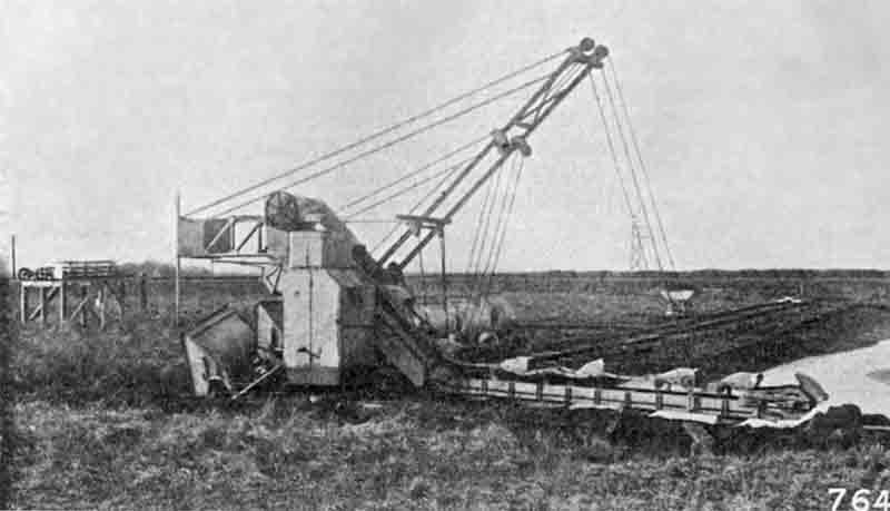 Figure 2. Multi-bucket excavator used in the marl/clay field. This could cut about 6 m below track level.
In common with most cement factories in the south of England, the raw materials employed are chalk and clay. The calcium carbonate content of the chalk varies from 97 per cent. on the higher levels to about 50 per cent. at the foot of the hills. An excavator of the dredger type, supplied by Messrs. M. Steenbrugge and Co., is used for digging the clay (Note 3); this machine is seen in Fig. 2, from which it will be observed that the digging is done mostly under water. The track on which the excavator runs is provided with a turntable so that the machine can be swung round when required and used for removing the top-soil. When digging clay the machine travels along the face, and at each new journey the jib is lowered so that the buckets take a fresh cut about ½in. thick. The clay is thus removed in thin layers over the whole depth of the pit. The jib is arranged to move round two pivots so that the part of the jib along which excavation takes place is always at the same angle, and the depth of cut is therefore the same along the whole face. The excavator buckets discharge into a hopper at the back of the machine. This hopper is fitted with a flap, which is operated by the attendant and allows the clay to fall into wagons which are hauled by a 2ft. gauge continuous rope haulage system to the washing plant. The chalk is excavated by a steam bucket excavator, and brought to the washing plant on a 4ft. 8½in. gauge track by a Diesel locomotive.
The washing plant consists of two Edgar Allen 18-ft. washmills working in series. The clay is tipped directly into the first washmill, but the chalk is first reduced by passing it through a set of Stag kibbling rolls from which it falls into the washmill in lumps of about 5in. downwards. From the first washmill the slurry is elevated by a bucket elevator and fed into the second washmill for further reduction. This washmill is of similar design to the first but is fitted with finer screens. Finally the slurry runs by gravity to a tube mill where it is ground to a fineness of about 5 per cent. residue on the 170-mesh sieve.
The mixture of chalk and clay is, in the first instance, controlled at the first washmill by regulating the number of wagons tipped of the respective raw materials. With a little experience it is possible to get very close to the proportions required, but adjustment is made by providing three storage tanks into which the slurry is pumped from the discharge sump of the tube mill by means of a Stag centrifugal pump; one tank contains slurry of the correct mix ready for the kiln, the second is being filled with slurry, and the contents of the third are being checked by the laboratory staff. If this is found to be, say, high in calcium carbonate, the requisite amount of low carbonate slurry is washed and pumped into the silo for the purpose of correction. For correction purposes it is also possible to mix the contents of any two tanks by means of valves and piping interconnecting the three tanks. Each tank is fitted with a series of air pipes through which compressed air is blown at regular intervals to agitate the slurry thoroughly and prevent settling of the solids. The compressed air is supplied by a Broom and Wade compressor of the horizontal rotary type direct coupled to its driving motor.
A three-throw Stag pump of the plunger type delivers finished slurry to main storage tanks in the kiln department. Water for the washmill is supplied by a three-throw Pearn pump which delivers water from a nearby stream into an angular storage tank incorporated in the design of one of the slurry tanks.
Two steel tanks, each having a capacity of about 16,000 cu. ft. of slurry (Note 4), are provided for storage purposes. These tanks are of the same design but larger than the correction tanks. With this storage capacity of finished slurry, the washmill section of the works can be closed down over weekends.
Two sets of Stag centrifugal pumps are provided to deliver the slurry to the kiln, one set being a standby. Regulation of the slurry feed is by a spoon feeder driven through a worm reduction gear by a variable-speed motor. The latter is controlled by the kiln operator from the firing platform.
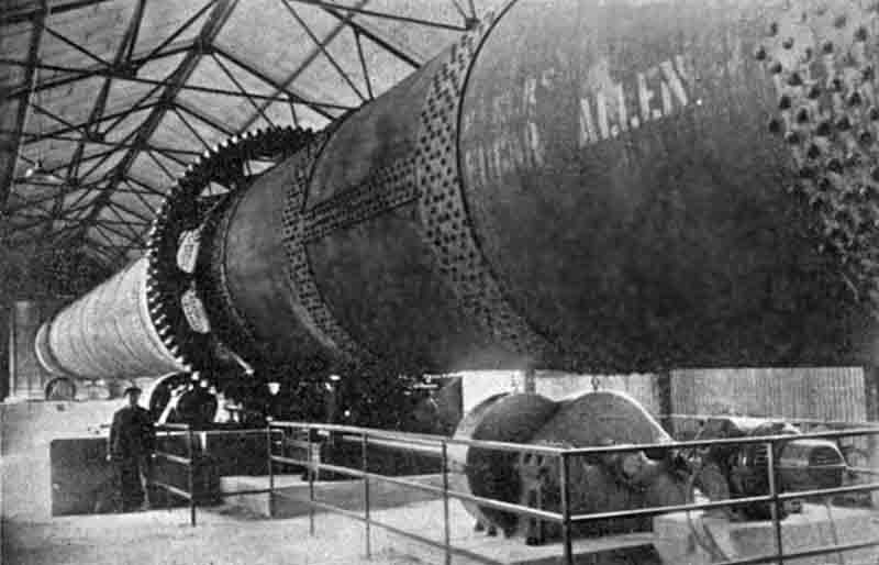 Figure 3. Kiln drive, viewed uphill. The drive pinion is nearly out of sight on the far side, driving the kiln anti-clockwise.
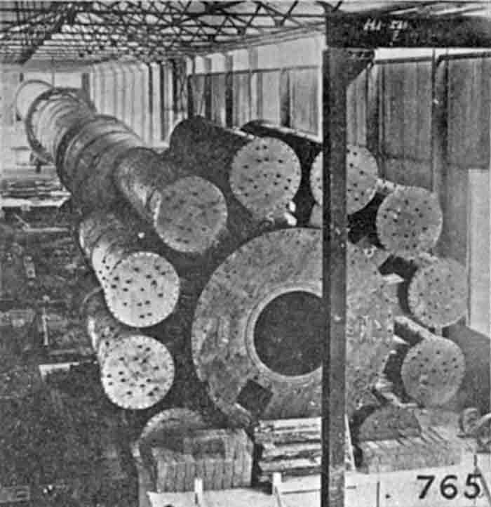
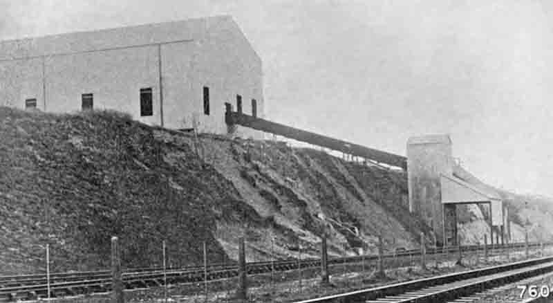 Figure 5. Coal tipped from rail wagons was raised by elevator and conveyed into the coal store by belt.
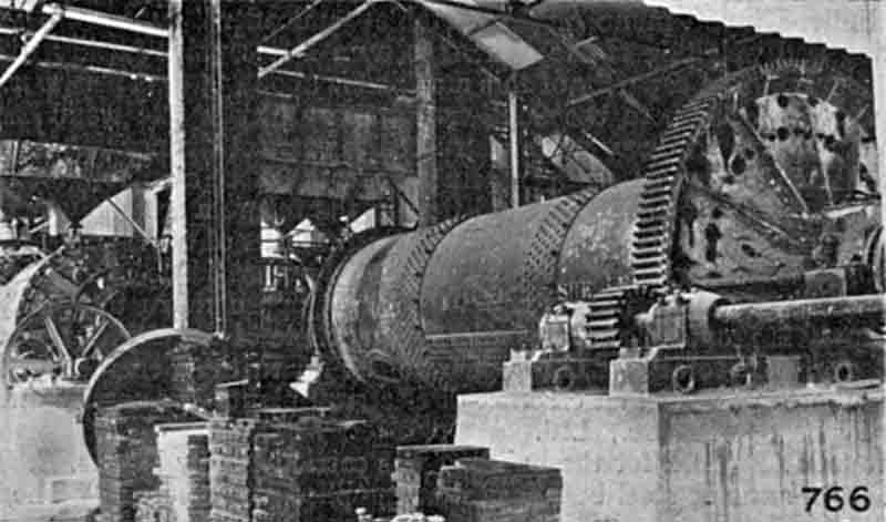 Figure 6. Cement mill house.
The Kiln
The kiln has an output of 60,000 to 70,000 tons of clinker per annum (Note 5), and there is room to accommodate two further units. The kiln is 9ft. in diameter by 235ft. long. The shell is lined with firebrick and has an enlarged section of 10ft. 6in. diameter at the clinkering zone (Note 6).
The kiln is carried on four cast steel tyres supported on chairs which are riveted to the shell. It is driven by a variable-speed motor direct coupled to an enclosed reduction gear. The speed is further reduced by open-spur gearing, and the final drive is through a spur wheel, mounted on the kiln shell, and transmitting motion to the kiln by tangential spring plates. The drive is illustrated in Fig. 3. The kiln is of the Edgar Allen "Tiger" type, and is fitted with a set of recuperator tubes secured rigidly at one end to the kiln shell and hinged at the other to allow for expansion. Clinker enters the tubes through openings in the shell at the end of the kiln, and travels up through the tubes assisted by spirals fitted inside. In addition, cascaders inside the tubes lift the hot clinker, thus exposing it to the air and reducing its temperature, and at the same time heat the air used for combustion. Fig. 4, taken during the erection of the plant, shows the discharging arrangements. A reduction in fuel consumption is obtained by this type of kiln as against older types with separate coolers, inasmuch as there is less leakage of cold air into the system, while construction costs are reduced by having a combined unit and less head room is required (Note 7).
Coal is received at the works sidings and discharged into a receiving hopper. Under the hopper a feeder is provided to deliver the coal to a vertical steel-cased elevator. The elevator discharges the coal onto a band conveyor, which takes it into the main coal storage shed where it is handled by a travelling crane and grab. The coal, which may have a moisture content of 16 per cent., is dried in an Edgar Allen double-shell rotary dryer, passing over a magnetic separator to remove any tramp iron. Reduction of the coal to the requisite fineness is accomplished in a Rexman rod mill (Note 8) working in conjunction with a Stag air separator. Fig. 5 shows the first stage of the coal-handling plant.
Clinker and Cement Handling and Storage
Coal, clinker and gypsum are stored in a covered building with retaining walls on all sides and cross divisions to separate the various materials. The building, which is 60ft. wide, is served by a crane running the full length. Wet coal is dumped within reach of the crane by the conveyor. The crane is thus able to distribute the coal, and when necessary mix different qualities of coal. The crane also feeds the raw coal hopper forming a storage for the coal drying plant. The clinker discharged from the kiln is conveyed by an Edgar Allen swing tray conveyor and elevator to a suitable height for delivery into the storage area. Previous to dumping it passes over an automatic weigher which registers the output of the kiln. A small area is reserved for gypsum.
The clinker mill house can be seen in Fig. 6. On the left one of the two Rexman rod mills can be seen. These two mills were used as preliminary grinders, their product being screened over two Edgar Allen—Allis-Chalmers vibrating screens which return the rejects to the rod mills and pass the fines to the tube mill for final reduction.
From the tube mill the cement is delivered by gravity to a Fuller-Kinyon stationary pump. The plant consists of a pump for moving the material, a pipe-line for the transport of the material, and switching valves in the pipeline for diverting the material to any desired point.
In order to expedite erection of the factory and reduce the initial construction costs, the usual type of cement silo was not built, but provision was made for the construction of such silos at a future date (Note 9). For the storage of the cement a set of four specification bins was constructed into which the Fuller-Kinyon pipeline delivered the cement, and from which the cement was extracted by another Fuller-Kinyon pump of the portable "unloader" type.
Packing and weighing of the cement is by a Bates valve packer with three delivery spouts. The capacity of this machine is about 35 tons per hour.
The works are close to the Southern Railway's main line from London to Newhaven. A new roadway was constructed to connect the packing department with the Lewes-Newhaven road. Facilities are therefore available for despatch by rail or road. It was contemplated that in the future a scheme would be put in hand to make use of the river Ouse as a third means of transport (Note 10).
The works are electrically driven by purchased power. The current is brought into the works sub-station at 11,000 volts and stepped down to 440 volts (Note 11). A second supply is provided at the quarry. The whole of the electrical equipment of the works, of a total of 1,600 HP, was sub-let to the General Electric Co., Ltd., and the cable work and erection of electrical plant were carried out by the Electric Super Service Co., Ltd.
The foundation work for the building was carried out by Messrs. E. D. Winn and Co., Ltd., and the steel buildings were supplied and erected by The London and Wales Steel Construction Co., Ltd.