Discussion of early tumbling mills is complicated by the fact that the terminology has changed. A Ball Mill was originally a short (compared with its diameter) mill with media consisting of steel balls, used for coarse grinding. A Tube Mill was originally a relatively long mill with media consisting of small pebbles, used for fine grinding. Later, mills that combined these two functions were called Combination Mills. However, since 1930, all mills have been combination mills, and are now called ball mills or tube mills, the terms being more-or-less interchangeable.
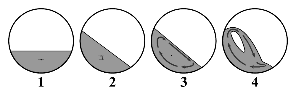
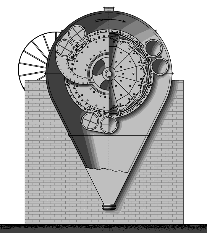
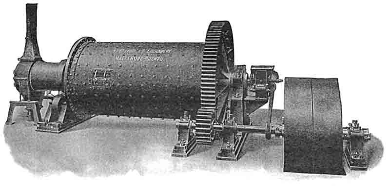
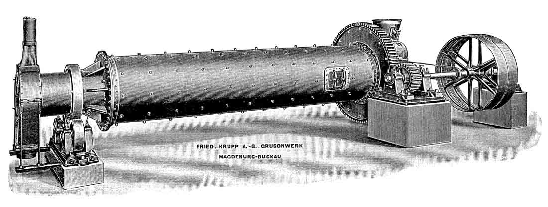
The first continuous tumbling mill to find application in the cement industry was patented in 1876 (Gebr. Sachsenberg, Rosslau, Sachsen-Anhalt) and after redesign by Jenisch and Lohnert, was manufactured by Grusonwerk (Dessau) in 1885. These were certainly in use in Britain by 1890. The mill was built around a drive shaft carried on bearings at either end. Between two end-plates, the drum was built up from steel castings in a slatted arrangement. The length of the drum was around 50-55% of the internal diameter. Steel balls at about 25% volume loading were the grinding media. The mill was run at around 50% of critical speed, since cascading of the charge was not desirable because of the central shaft, and to avoid breaking the peripheral castings. Feed entered the mill through slots around the shaft on the inlet end-plate, and fine material ran out through perforations in the slatted castings. Surrounding this was a network of sieves that allowed the fines through, while coarser particles were carried up and dropped back into the mill. The whole mill was surrounded with a dust enclosure to catch the fines, which in practice were thrown out in all directions. The mill as described would draw power P = 2.3 D3.5 kW where D is the diameter inside the lining in metres, so a 2 m mill would draw 26 kW at the shaft and might grind 2-3 t/hr on coarse grinding duty. After Grusonwerk was acquired by Krupp in 1893, it was known as the Krupp Grusonwerk Ball Mill. The working principle was used by other manufacturers and mills of this type were still being produced up to WWI. Later designs attached half-shafts to the two mill end plates, avoiding having the shaft pass right through the mill.
As has been discussed, mills that rely upon sieves for their fineness control may be suitable for rawmix or coal grinding, but for cement, particles leave the mill as soon as they are just fine enough to pass the sieve, and the ultra-fines needed for cement strength are not produced in quantity. For this reason, such ball mills were only used as a pre-grind stage, followed by - for example - flat stones. In 1904, Krupp produced a self-contained cement mill using a ball mill and their version of the Askham separator in closed circuit, but I think this was never used in Britain. However, from the mid 1890s, ball mills were used in combination with tube mills (see below) and this setup became the normal cement milling installation until 1920.
Modern ball mills
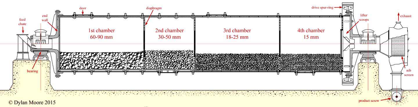
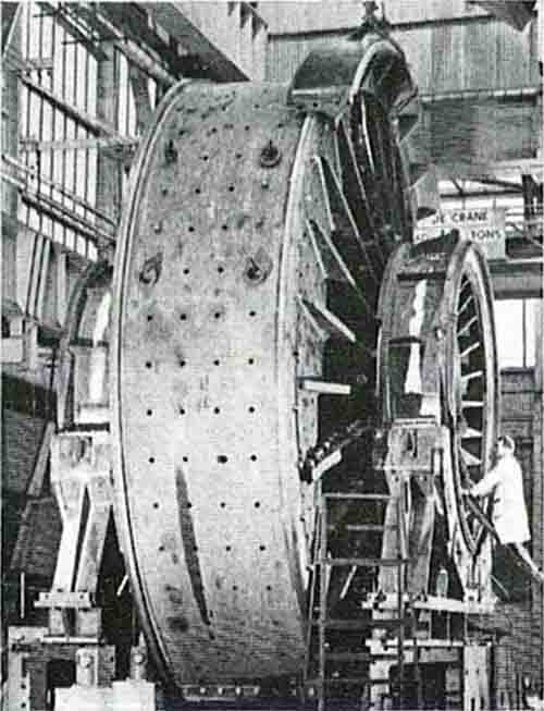
1930s four-chamber ball mill for cement
From 1920, the transitional "combination" mill morphed into the simple multi-chamber design that was standard for the ensuing eighty years. A mill now consisted of a single cylindrical steel shell, closed at both ends by cast steel end-walls, from each of which projected a concentric trunnion. The mill was supported on bearings on the trunnions. The size of the trunnions had increased to the extent that normal-sized crushed stone or clinker could be fed to the mill. Large particles need large media, with high momentum, to crush them. On the other hand, to grind small particles, the large surface area provided by small media was needed to provide the necessary attrition. For grinding large particles down to finished product in a single mill, it is necessary to use successively smaller media, which must be prevented from mixing with each other. The simplest solution was to divide the cylinder into a number of chambers with perforated diaphragms that allowed the ground material through, while keeping the media sizes separate.
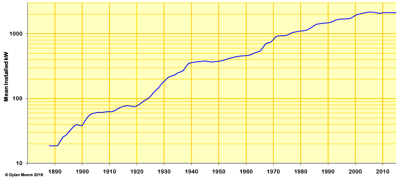
The basic technology of these mills was well established by the mid 1930s, and remains more-or-less unchanged today. During 80 years, there has been a steady increase - ten-fold overall - in capacity, and this has been accompanied by improvements in the alloys used in the wearing parts and in the details of the bearings and drive.
Typical mills in the 1930s had drive power in the range 300-1000 kW, while typical modern mills have ten times these ratings, and there is no obvious upper limit to future developments, although the poor energy efficiency of the design means that the cement industry will not see larger mills.
The development of all-steel media allowed maximum grinding effect in these mills, but the rate of wear of these media was very high, often around 1 kg per tonne of material ground. Although hard alloys were available, they tended to be brittle, and hard media would break into irregular pieces, causing a rapid reduction in grinding efficiency. It was preferable to have media that wore fast but maintained their shape, and chilled white iron was most commonly used for media and liner plates. Periodic sorting of the media with screens allowed the more worn media to be used in the next chamber of the mill, with most of the "top-up" media being added to the first chamber. The development of alloys that were both hard and tough - mainly chromium steels - began in the 1950s, but these alloys were expensive, and it was not until the early 1970s that their price was reduced sufficiently to eliminate the use of softer steel. On modern, large mills, the use of chromium steel alloys for media and liner plates is indispensible.
The original mills were turned by means of a spur ring meshing with a pinion. This was connected to an electric motor, usually through a gearbox. Because conditions were often very dusty in mill houses (or wet in wet-mills) the drive shaft was usually run through a wall, with the gearbox and motor in a separate, "clean" room. From the 1950s, it became common to dispense with the spur-ring, and drive the mill directly through a concentric shaft attached to the outlet end trunnion. This became less viable with larger modern mills, but an alternative drive philosophy for these that is occasionally encountered is the "wrap-around" induction motor delivering torque directly to the mill shell, so that drive bearings and gearboxes with their frictional losses are no longer required.
The classic bearings for these mills consisted of cylindrical "low-friction metal" surfaces, separated by a film of oil. Oil is continually pumped into the gap, and control systems automatically stop the mill if the oil pressure drops or the temperature of bearing elements rises due to friction. As the size of mills increases, the pressure needed to lift the mill on its trunnions increases beyond the viscous capacities of lubricants, and in order to provide more bearing area, modern large mills dispense with trunnions, and run instead on pads bearing on a slip-ring on the mill shell itself.
A significant development in mill design occurred with the introduction of the classifying liner plate. These plates provide a conical surface sloping towards the inlet, which bounces cascading balls towards the inlet. This effect is greatest for the largest media, and as a result, the larger media congregate towards the inlet, while the smaller madia are displaced towards the outlet. This potentially allows the removal of diaphragms. Classifying liners are usually thicker than conventional plates, so that the mill diameter is reduced, with a potential reduction in mill capacity only slightly offset by the increased effective length of the mill provided by removing the diaphragms. However, the mill is simplified, and draught through the mill is freed up, so modern mills generally have only two chambers: the first with a lifter lining, and a much longer second with a classifying lining. In a few instances, single chamber mills have been designed, with classifying lining throughout.
Ball mills for raw milling
For raw milling and coal milling, it is not necessary to produce ultra-fines, so two-chamber mills were most common. The development of the multi-chamber mill corresponded with the abandonment of dry process in Britain, so raw mills were used to grind slurry. In hard-rock areas making slurry with ball-mills, the raw- and finish-mills were very similar, and were often installed side-by-side.
Although rawmix components are generally softer than clinker minerals, any quartz content makes the mix very abrasive, and wear is exacerbated in wet milling conditions. In the case of linings for wet mills, the wear problem was solved by use of rubber liner plates, which are not corroded and resist abrasion. Grinding continues to occur primarily by abrasion between the media.
In the case of dry process rawmilling, early plants preceded the raw mill with separate driers. With the arrival of the new dry process in the 1950s, it was desirable to combine the drying and grinding processes. It was also necessary run the mill in closed circuit, using a separator. Where ball mills were used in Britain, four different process designs were tried:
- double rotator mills
- semi-autogenous mills
- drier + single chamber mills
- air-swept mills (including coal mills)
On modern installations, ball mills have been entirely supplanted by more efficient roller mills.
Double rotator mills
Double rotator grinding circuit
The Double Rotator® was the design supplied by Polysius, and used at Cauldon, Weardale, Aberthaw, South Ferriby, Cookstown and Rugby. Although in theory hot kiln exhaust gas could be used to heat the mill, only the Aberthaw mill did this. The Rugby mill uses cooler exhaust gas, and all the others used separate furnaces to generate hot drying air. The design has the advantage that both first- and second-chamber product pass through the separator, so that softer components that grind finely in the first chamber are removed and avoid over-grinding, while the second chamber can be graded to deal with the harder components only. At Cauldon, Weardale and Cookstown, the mill was preceded by an Aerofall mill and performed only regrind duty.
Semi-autogenous mills
7 m Aerofall mill being installed at Weardale
Semi-autogenous mills are used for grinding coarsely-crushed damp ores, and the grinding action is obtained in part by the rock itself ("autogenous grinding"). The few installations in Britain (Cauldon, Dunbar, Weardale, Cookstown) have all been Aerofall Mills. These were all the same size: 7 m diameter by 2.2 m long, with a 1350 kW motor, grinding 150-200 t/h of raw material. They ran on wide inlet and outlet trunnions, allowing a 1.3 m diameter feed space, and were fed with material 250 mm down. About 15% volume load of 130-150 mm media were used, and the mills maintained about 30% full. The mills were air-swept, requiring about 70 m3/s to carry out the product. The mills were followed by three-stage separators, which separated 30% of the product as of rawmix fineness, the remainder going to regrind mills.
Mills with drying and grinding chamber
The FLS dry rawmill design had a drying chamber, followed by (usually) a single grinding chamber with a classifying lining, operated in closed circuit. Only two of these were installed in Britain and Ireland, at Padeswood and Platin. Although it was feasible to heat these with kiln exhaust gas, in practice hot air was supplied from auxilliary furnaces.
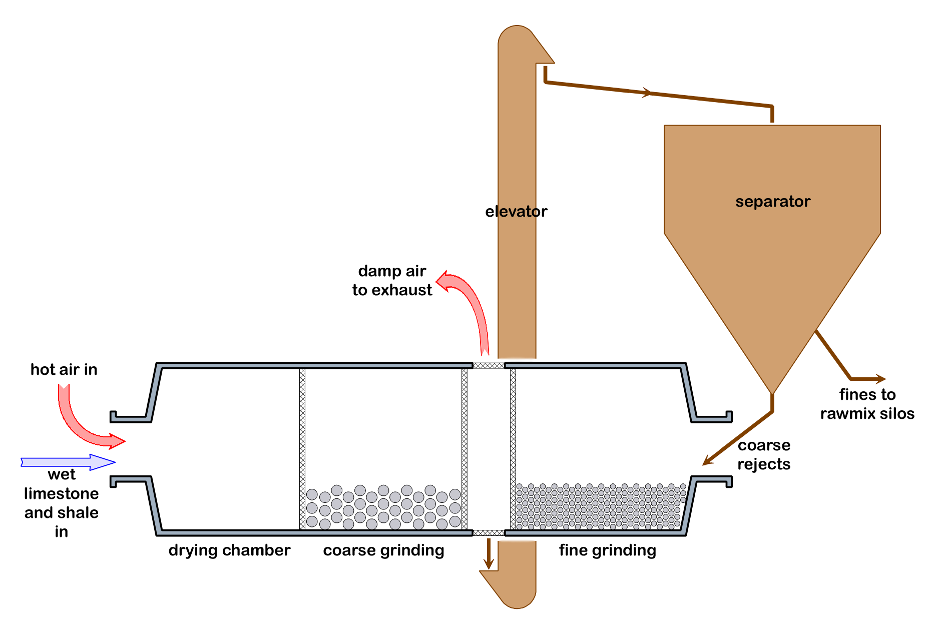
Air-swept mills
The first raw ball-mills to be designed specifically to be heated by kiln exhaust gas were those designed in the early 1950s by KHD as part of their suspension preheater kiln process, and were often known as Humboldt mills. Various other suppliers subsequently produced similar designs. In Britain and Ireland, the only installations were at Plymstock, Hope, Limerick and Derrylin. The mill is swept with hot gases from the kiln exhaust, suitably diluted with ambient air to avoid overheating the bearings. The large gas mass-flow is capable of lifting all the product in suspension. The rawmix-laden gas is then led into the kiln's gas filtration system: the solid product is passed through a separator, and any oversize is returned to the mill inlet. The system has the advantage that the sweeping gas need not be dust-free: the dust that leaves the preheater - typically 10% on clinker - is drawn through the mill, and is cooled and wetted by the grinding process, making subsequent filtration much more efficient. It also ensures that the dust is well homogenised with the rawmix before return to the kiln. However, rawmills are always designed with excess capacity to allow for maintenance time and for periods of reduced output, so for times when the rawmill is stopped, a parallel gas-cooling system must be provided.
When fuel was ground by ball-mill single-chamber air-swept mills were used from the 1920s, operated in indirect or semi-indirect mode. For 40 years, most FLS installations had "Tirax" ball mills and indirect firing. Edgar Allen had a similar arrangement. These mills usually removed the requirement for a separate coal drier: with hot sweeping air, the fuel could be dried and ground simultaneously. The hot air was usually extracted from the kiln hood, but was sometimes provided by a separate furnace. The hot air supply temperature was controlled by bleeding in ambient air so that the coal/air mixture leaving the mill was below the 80-100°C upper limit to avoid explosive conditions. All such installations were further protected with explosion doors.
Ball mills for cement milling
The early multi-chamber mills had typically 3 or 4 chambers. A typical four-chamber mill might have:
| chamber | length, m | ball size, mm | % VL | mass, t | DAWN kW |
|---|
| 1 | 3.89 | 90, 80, 70, 60 | 29.2 | 23.12 | 253 |
| 2 | 2.29 | 50, 40, 30 | 34.1 | 15.75 | 161 |
| 3 | 3.89 | 25, 22, 19 | 27.0 | 22.35 | 259 |
| 4 | 2.84 | 16 | 26.7 | 16.00 | 186 |
| total | 12.90 | | | 77.22 | 859 |
As discussed above, it became common to install classifying linings to the outlet chambers from the 1960s, and new mills commonly had only two chambers.
Closed circuit mills (with separators) were rarely installed, from the 1930s, but became common from the late 1960s, and recently-installed mills are exclusively closed-circuit.
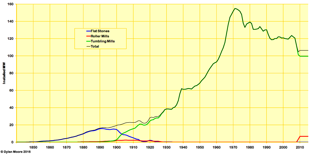
| Evolution of types of tumbling mill used for finish milling |
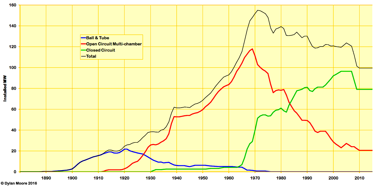 |
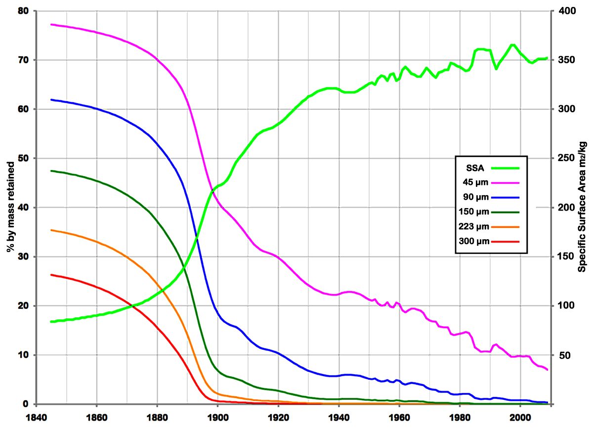
During the period of development from 1930 to date, cement mills have increased in size and drive power, in response to an increase in fineness of cement, an increase in the hardness of clinker, and a desire to operate a smaller number of grinding units.
| Mean installed power of tumbling mills used for finish milling |
 |
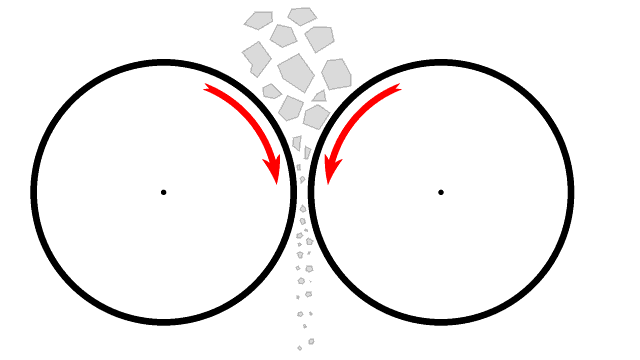

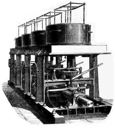
 Dutrulle & Solomon Edge Runner 1886
 Neate's Dynamic Grinder: picture from Engineering, 31/1/1891, 51, p 131
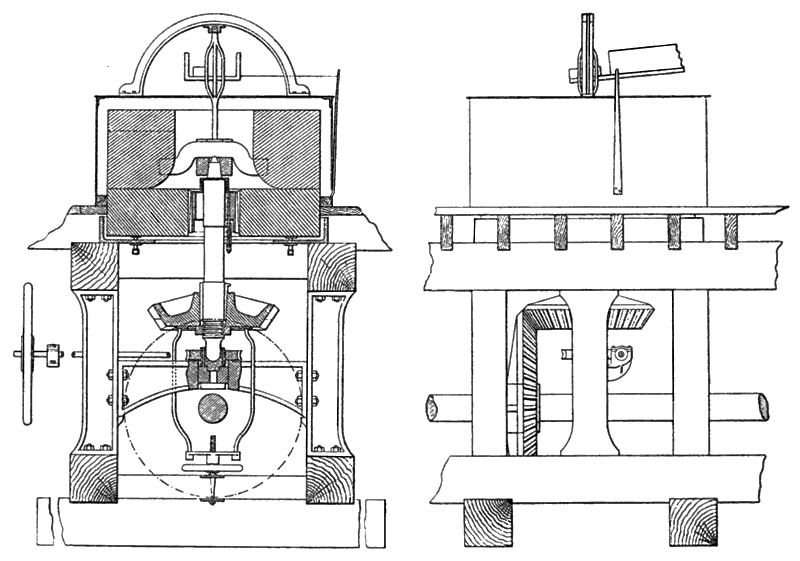
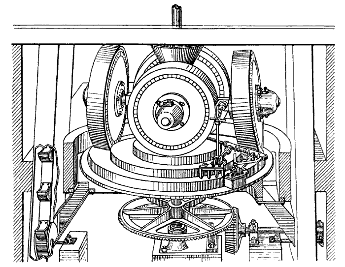
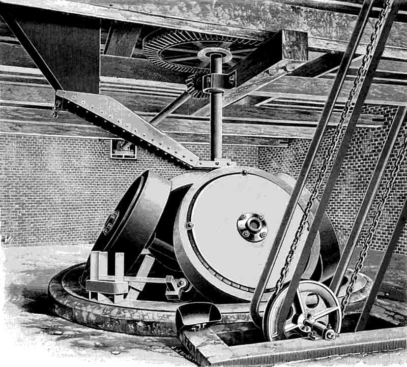
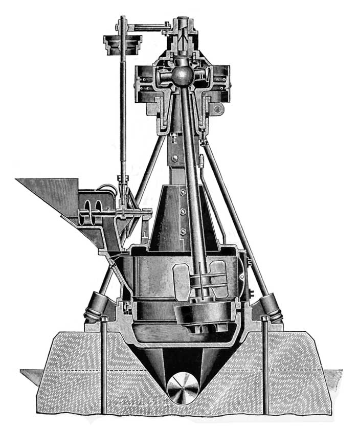 Griffin Mill
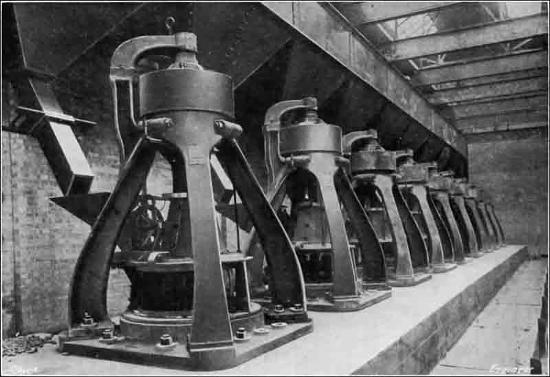 Griffin mills in use for cement grinding at
 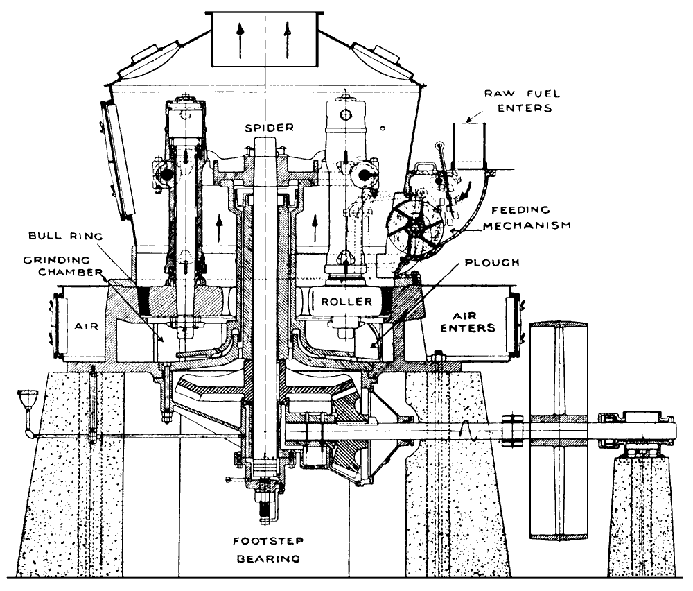 Raymond Mill
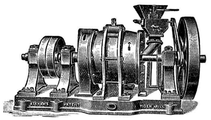 Askham's Tiger Mill
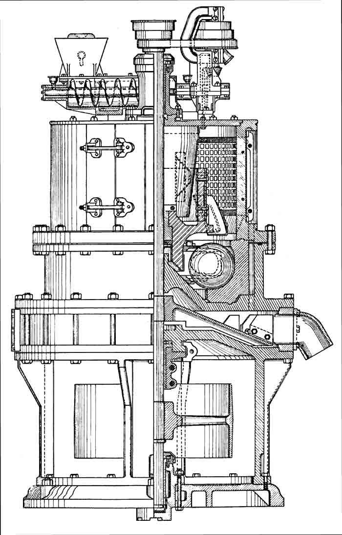 Fuller Lehigh Mill
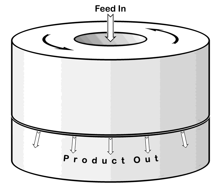
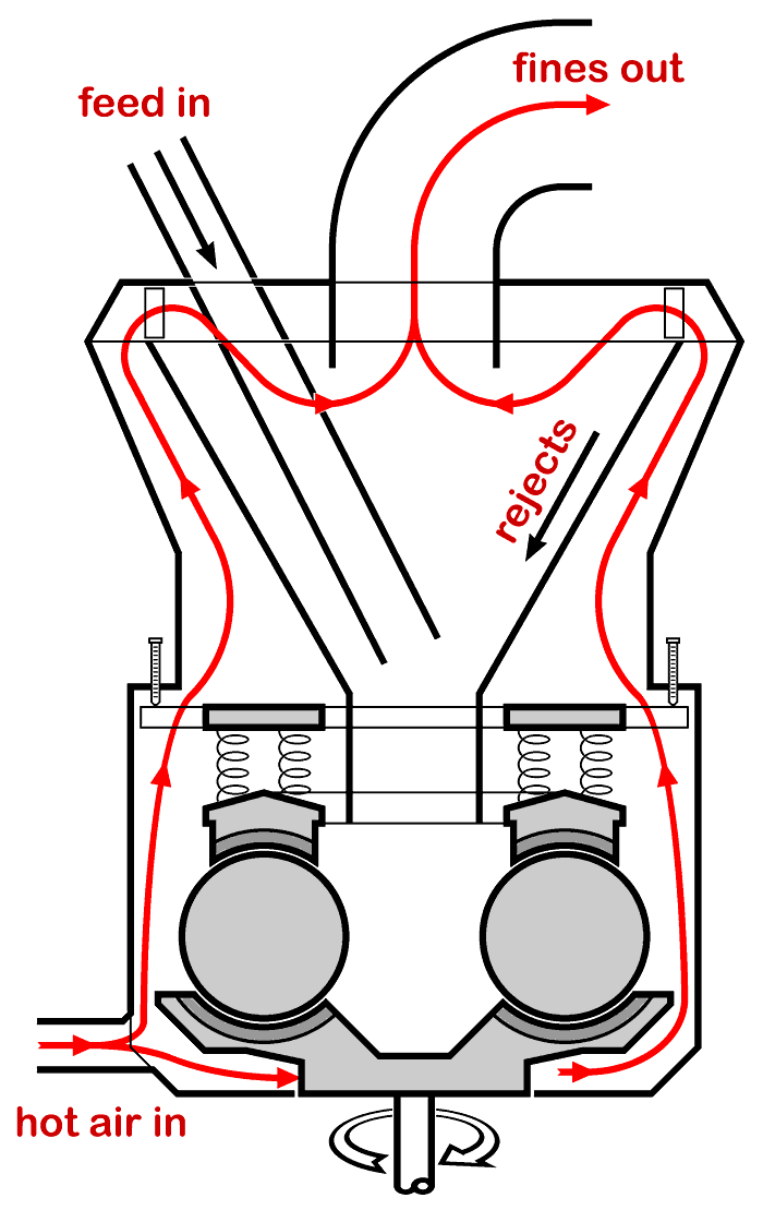 Essential design of ball-race mills with vertical pressure and a spinning table
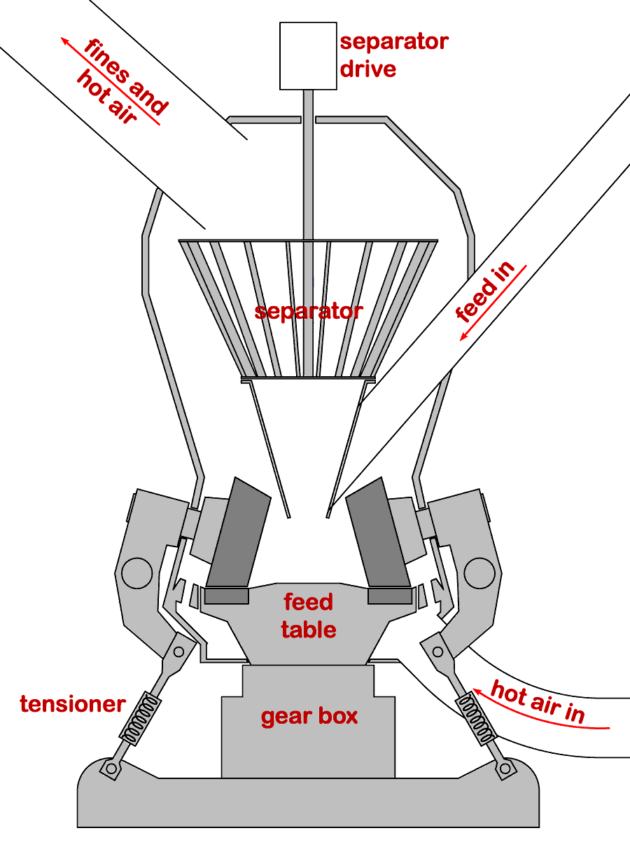 Essential design of modern roller mills
 Picture: ©Alan Murray-Rust 2015 (modified), and licensed for reuse under this
 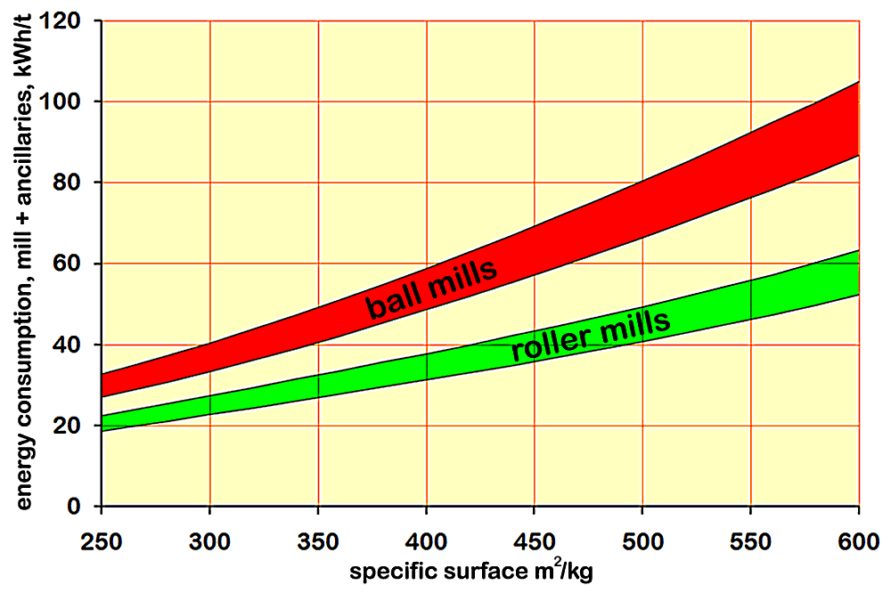 Power requirement for cement grinding by roller mills and ball mills
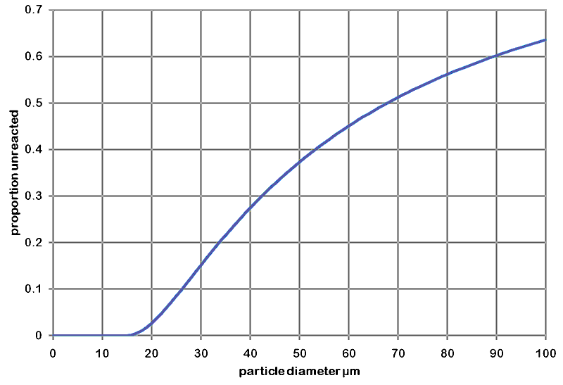
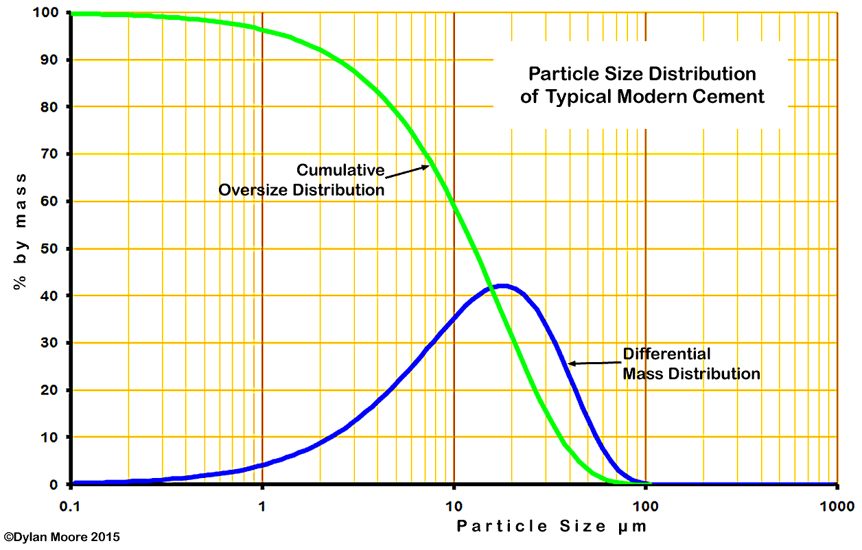
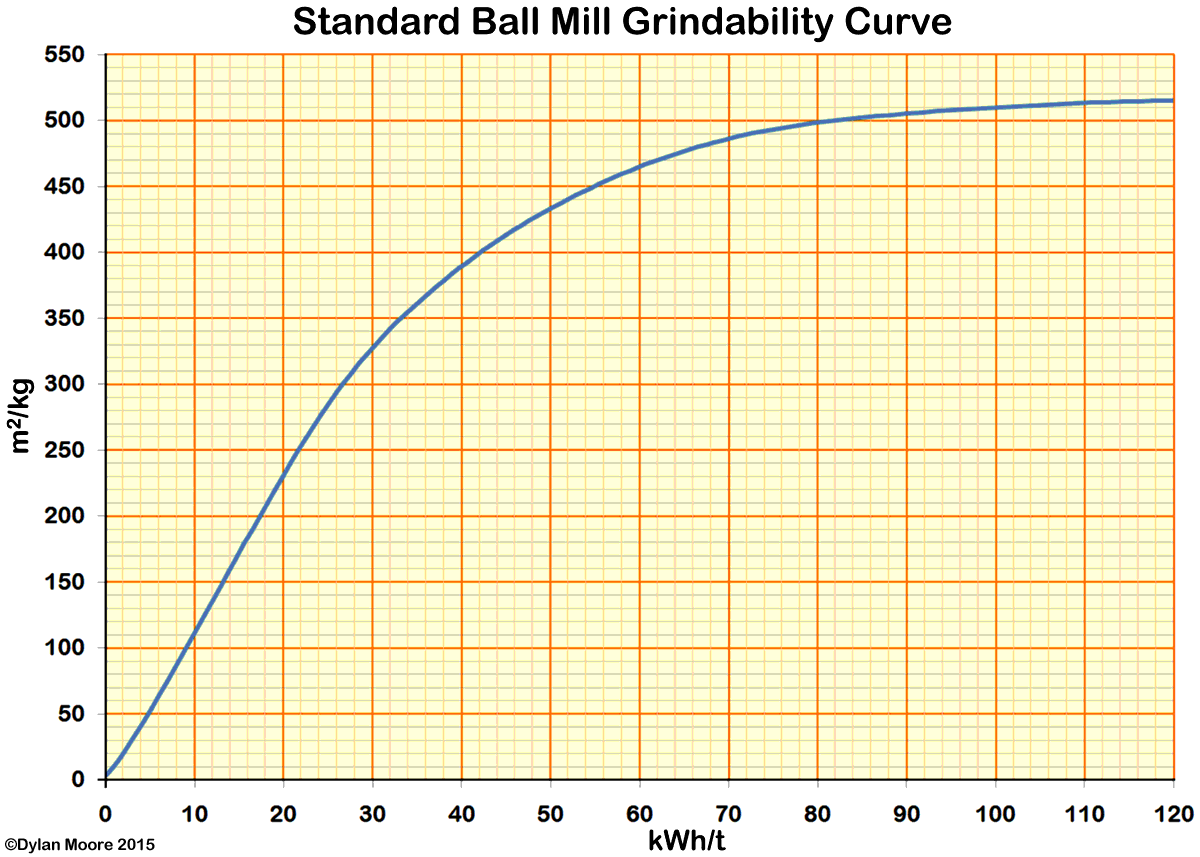 The "standard" curve for well-tuned ball mills was derived for cement typical of the 1920s: modern clinkers tend to be harder, and the energy cost for modern cements is generally higher than indicated here.
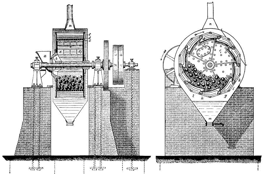 Early Krupp Grusonwerk ball mill
 Early Kominor mill
 Later Kominor design with cylindrical sieve mountings ("Fastax") for extra area and accessability
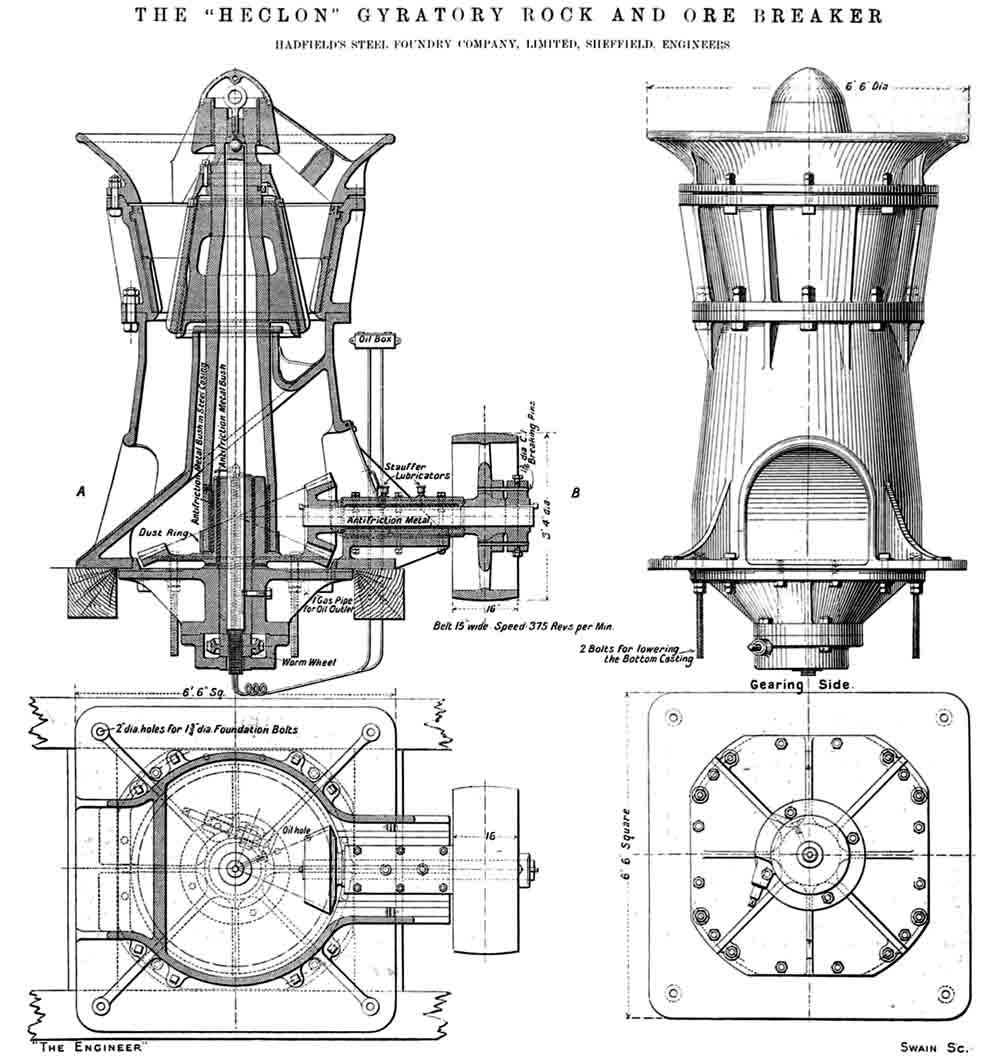
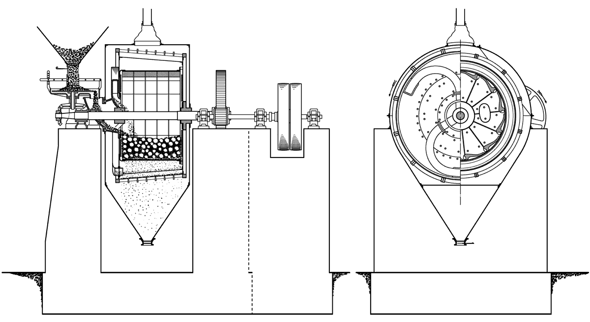
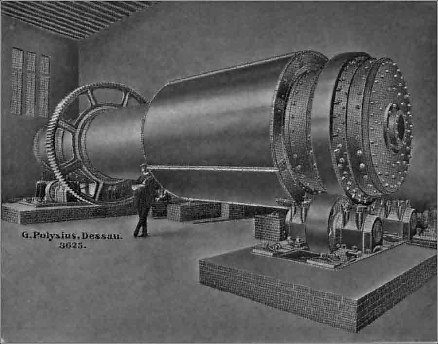
 Krupp ball mill with trunnion discharge (1907) as installed at
 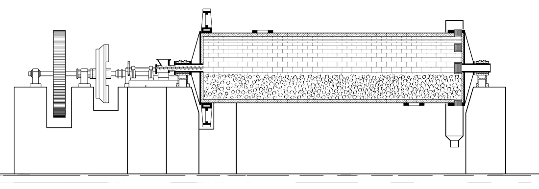 Davidsen tube mill
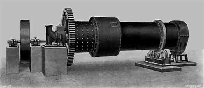
 Krupp tube mill with trunnion discharge (1907) as installed at
 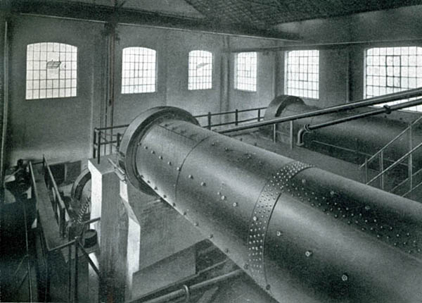 Tube mills for wet rawmilling at
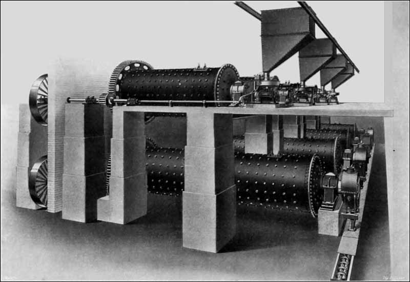
 The Polysius Solomill
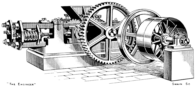
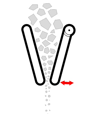
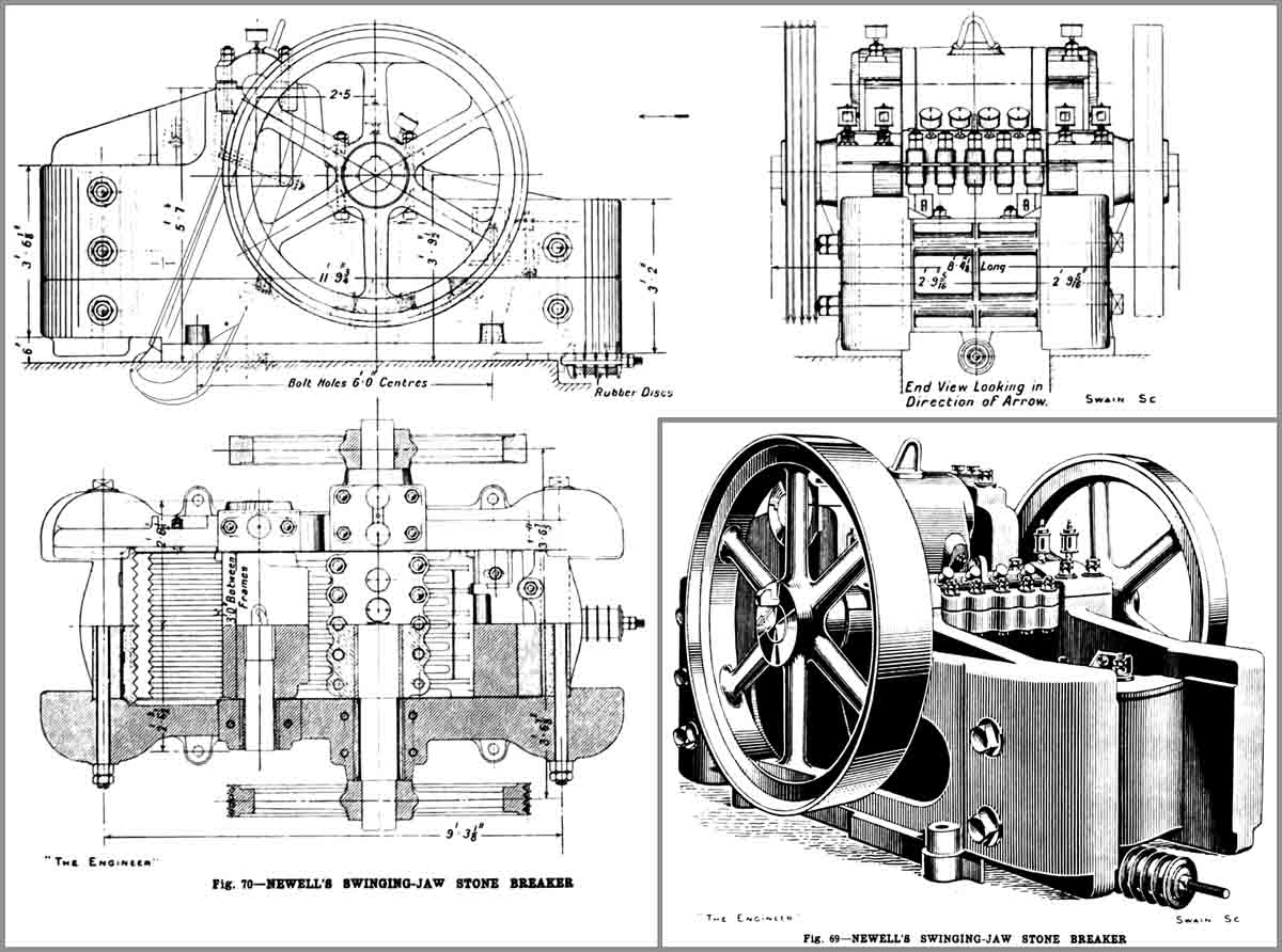
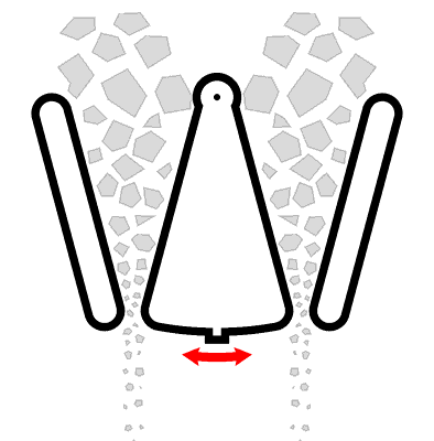
 Newell's chamber grinding mill
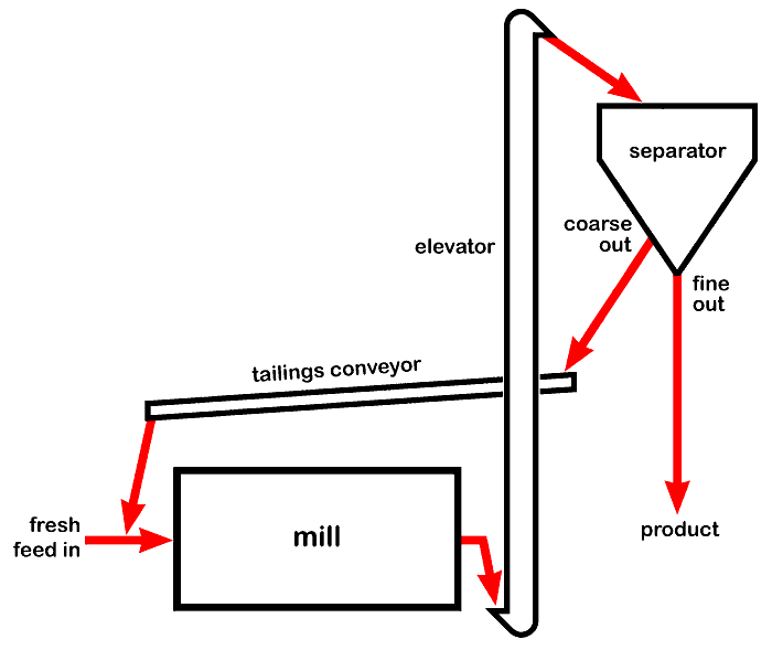 Closed-circuit grinding

 1920s FLS Trix Separator
 120 degree DSM Screen
 Hydrocyclones
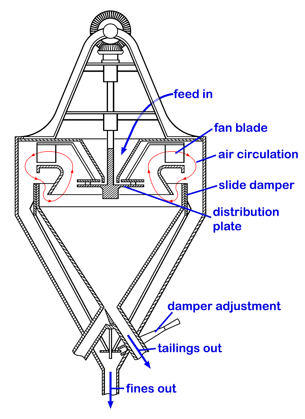 Askham Air Separator, based on the patent drawing
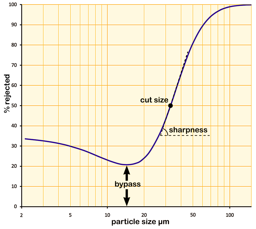 Tromp curve
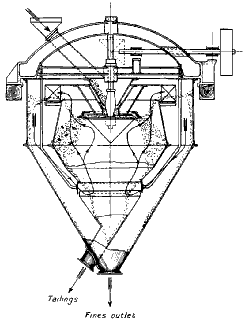
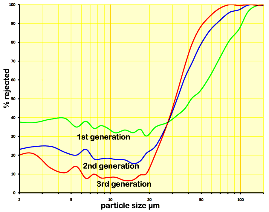 Development of air separators
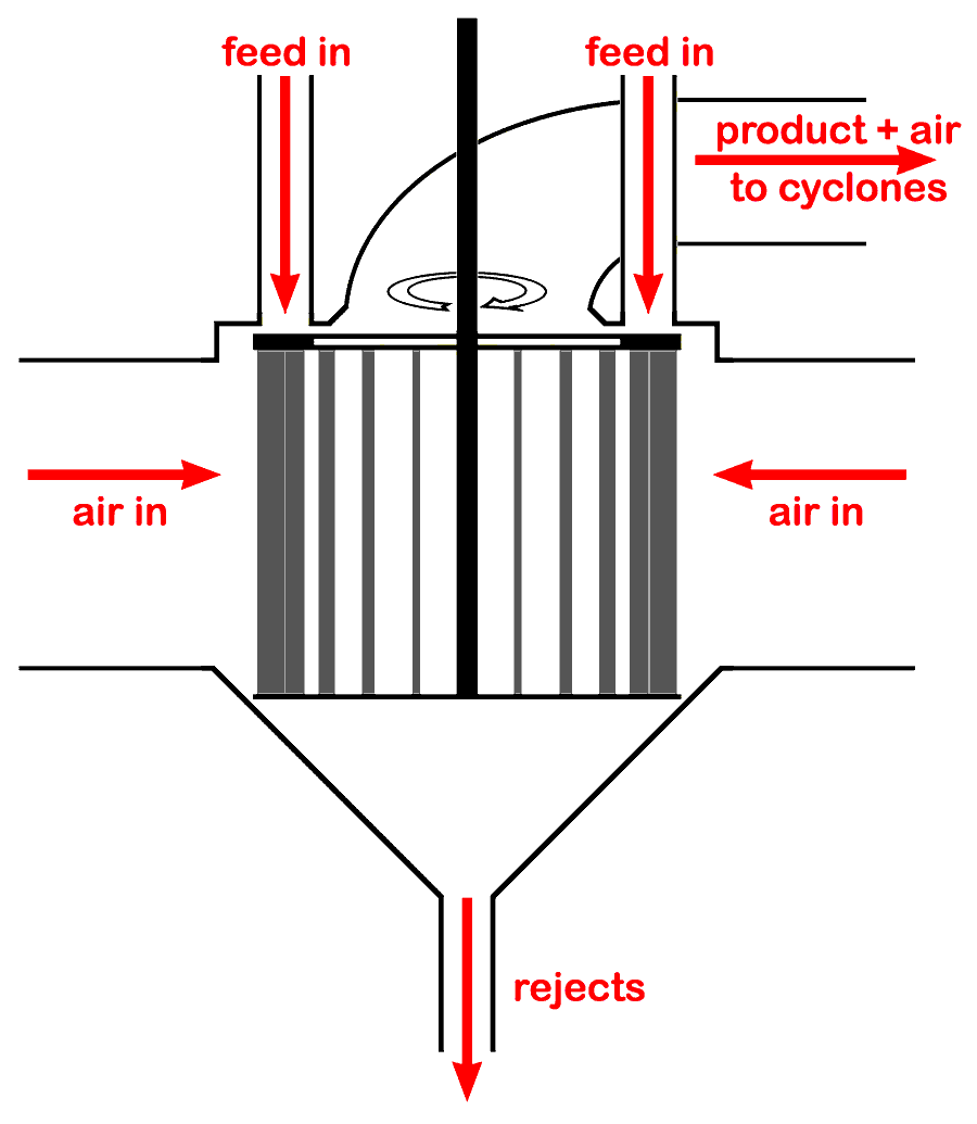 3rd generation separator principle: spinning cage separator