The following is a transcript of anonymous articles that appeared in The Engineer, CVII, 1 Jan 1909, pp 8-9 & 12, and 8 Jan 1909, pp 28, 29 & 38.
Southam was the first of the five Warwickshire cement plants to install rotary kilns, and was also the first plant using Blue Lias materials to adopt the dry process.
The plant was an old-established site making hydraulic lime, and, from around 1875, Portland cement. Among all the Blue Lias plants, only Penarth had tried rotary kilns - and this was the false-start of the very early Stokes kilns. By the early 1900s, all the Warwickshire firms were interested in trying the new, improved process and all four converted to rotary operation before WWI. Kaye's happened to be the first, and used the well-respected William Gilbert consultancy for design advice. The selection of the by-then rather backward Fellner & Ziegler equipment gave them perhaps a slight disadvantage compared with the others, and the dry process chosen was soon to be abandoned. Although Southam was an excellent cement making site, like the other four surviving Warwickshire plants, it very nearly went under in the depression of the early 1930s. It was saved when taken over by Rugby, and an aggressive investment programme replaced most of the equipment shown here with an "off-the-peg" FLS wet process plant. The site finally closed when Chiltern chalk - apparently the only possible raw material in Warwickshire - was cheaper and easier to deliver to the expanded Rugby plant.
CEMENT WORKS AT SOUTHAM.
The cement works of Kaye and Co., Limited, are situated at Southam, which is on the branch line of the London and North-Western Railway joining Weedon and Leamington. The works have been built alongside the railway, and there are sidings running into it. What is known as Kaye's Arm of the Warwick and Napton Canal also enters the works, this canal forming part of the direct waterway communication between Birmingham and London. There are hence excellent facilities for the importation of the only raw material needed - coal - and the export of the finished cement (Note 1). Works were first started there in the year 1854 by the late Mr. Oldham, of Southam, who realised that the deposit of limestone in the district was exactly the material with which to make cement. This gentleman, however, does not appear to have done very much, for in the year 1868, when the works were taken over by the present owners, but a small quantity of cement had been made, and that of the type of the Roman cements then most in vogue. The late Captain Lister-Kaye, R.A., father of the present managing director, perceived that the raw materials were capable of yielding a much stronger article, and it was not long after he started operations that a cement was made that was found to possess all the properties of first-class Portland cement. From that time the history of the firm has shown steady progress, improvements and additions being made from time to time. When rotary burning had to be considered the management decided that it would be a better policy to lay down an entirely new plant than to attempt to adapt the existing works to the new system. New works were accordingly built adjoining the old, and they were erected to the design of Mr. William Gilbert, M. Inst. C.E., who worked in conjunction with Mr. D. B. Butler, A.M. Inst. C.E., the actual erection of the works being superintended by Mr. A. H. Bristow, A.M. Inst. C.E.
At the old works the necessary proportions of stone and shale or clay were passed through a Mason crusher, from which they were elevated to the "raw mill", which consisted of a set of millstones made of the hardest selected French burrs. These reduced the materials to a fine powder, which was then conveyed to mixing pans, where, with the addition of water, it was made into a stiff slurry (Note 2). This slurry was dried by spreading it on floors which were heated by having exhaust steam passed beneath them. When drying was complete the desiccated "compo", as it was called, was placed in alternate layers with coke in pot kilns and burnt. When calcination was complete the grinding of the clinker was brought about by the use, first of all, of French burr millstones, and afterwards of two horizontal tube mills. The ordinary grade of fineness was that which gave only a 6 per cent. residue on a 76 by 76 mesh sieve (Note 3). The cement was of excellent quality, but we understand that, since the new works have been started, manufacture by the older method has been discontinued. The making of hydraulic lime, which was carried out at the old works, still goes on. The limestone—the same as that which is used for the production of cement —is burnt in kilns with coke, the carbon dioxide being driven off and the oxide of calcium or lime remaining.
We have already referred to the limestone deposit of the neighbourhood. This forms a belt of considerable extent, stretching for miles in the direction south-east of Leamington. The deposit consists of alternating and well-defined layers of stone and clay of the lower lias formations. The following table gives analyses of the product of the quarry as a whole, of the clay and of the stone: —
| Analysis of raw materials | Stone and | Clay % | Stone % |
|---|---|---|---|
| Clay % | |||
| Water & organic matter | 3.02 | 4.78 | 2.27 |
| Silica (SiO2) | 11.99 | 29.36 | 8.98 |
| Oxide of alumina (Al2O3) | 4.80 | 10.80 | 3.85 |
| Oxide of iron (Fe2O3) | 1.88 | 3.19 | 1.09 |
| Calcium carbonate (CaCO3) | 76.64 | 45.66 | 82.11 |
| Magnesia (MgO) | 1.10 | 2.42 | 1.00 |
| Sulphuric anhydride (SO3) | 0.26 | 0.22 | 0.61 |
| Alk. and loss | 0.31 | 3.57 | 0.09 |
| 100.00 | 100.00 | 100.00 |
It will be observed that, whereas the stone has a calcium carbonate content in excess of that which is required for the manufacture of Portland cement, the clay is considerably less rich in this substance. A proper mixture of the two ingredients produces a raw material which contains exactly the proportions required for the manufacture of Portland cement of high quality.
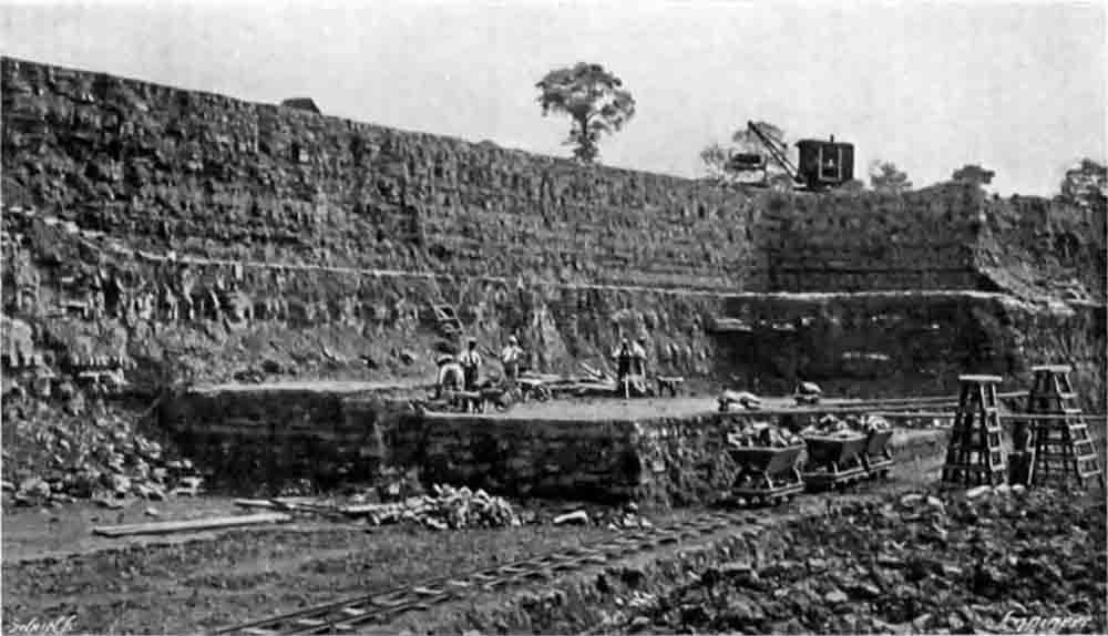
An exceedingly interesting part of the works is the quarry, which is being worked in a business-like and thorough manner. The strata of stone and clay are well defined, which facilitates accurate blending and proportioning. Moreover, the stone is a good deal fissured and is loosely packed, so that quarrying is easy and no blasting is required. The materials are got out at several levels, as may be seen in Fig. 5, which is a view looking approximately south-east and away from the works. We may here say that the strata are almost horizontal, though there is a very slight dip towards the workings. This dip is not enough, however, to cause trouble with water, and when this shows signs of accumulating it is readily got rid of by digging a sump down through the 6ft. or so of clay (Note 4) which forms the working bottom of the quarry, and draining the water into it. The water then sinks through to other strata and disappears. The depth to which the workings extend is about 40ft., and as at this level the 6ft. bed of clay was encountered, it was decided not to go any deeper. Lines of light railway are run at various levels, and the materials are loaded into tipping trucks and hauled from the quarry by means of small locomotives—see Fig. 6. Some of the trucks which are filled at the intermediate levels are lifted bodily by jib cranes and dropped on to the rails at the upper level. Up till some little time ago horse haulage only was employed, but we understand that the introduction of the locomotives and cranes has very considerably reduced the cost of quarrying.
 |
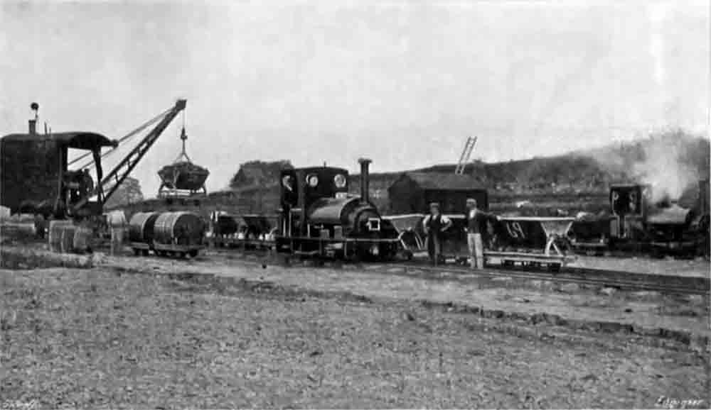 |
| Fig. 5 - Quarry face, showing stratification. The stone is being separated from the clay by hand. Slabs of stone are lifted by pick and bar. As at other Lias quarries, the stone layers ("floors") had individual names, and distinct chemical properties, and were processed separately. | Fig. 6 - Locomotives at the top of the quarry. |
The distance from the quarry face to the works is something over a quarter of a mile, and the railway line just before it reaches the latter passes over a weighbridge. Each separate truck of material is weighed, and as all the tare weights of the wagons are known, an accurate record is kept of all the material going into the works.
Chemical analyses are being continuously carried out, and the subsequent operations are all performed in accordance with instructions from the chemical department. The stone and clay are hauled up an incline which has been constructed above a stone crusher feeding platform and are there shot. A certain amount of storage space is necessary, since, though the works are in operation continuously, the stone and clay are only quarried in the daytime. The stone crusher is of the Hadfield type, with which our readers are familiar—see The Engineer, October 28th, 1904.
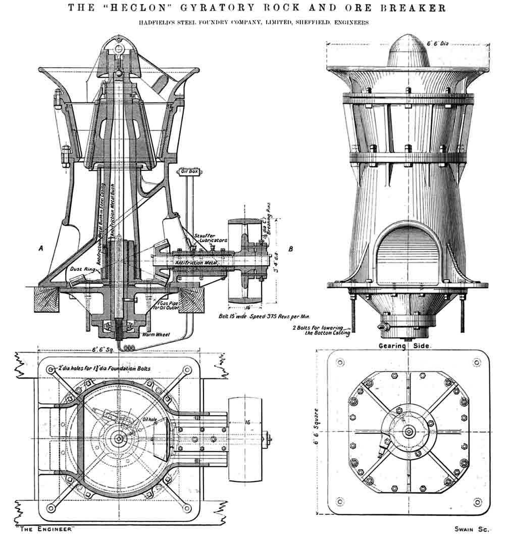
The crusher shown in the 1904 article was rated at 100 t/hr. Scaling from the plan, the Southam one was probably about 5 ft diameter and crushed perhaps 50 t/hr. Plant raw material throughput was around 1600 t/week. |
In this the stone and clay are broken up into small pieces and delivered on to a rubber band conveyor, which, in its turn, delivers the broken pieces into the feeding shoot of a two-roll Hadfield crusher (Note 5), where they are still further broken up, finally falling into a bin constructed to hold about 150 tons, and erected in a chamber excavated below ground level. The first Hadfield crusher is driven by a 86 brake horse-power Thomas Parker motor, and the second by a 26 brake horse-power motor by the same firm, these being contained in a separate room, to protect them from dust. The discharge from the bin is through an automatic percussion feeder on to another belt conveyor, which travels up through an inclined tunnel made of armoured concrete, to ground level, and thence up an inclined staging to the hopper of the shoot leading to the drying drum. This band can convey the broken stone at the rate of eight tons per hour. The materials, after passing through the two sets of rolls, are broken up into very fairly small pieces; at any rate, they are small enough to ensure their being properly dried in passing through the drum. A section through the stone crushing plant is given in Fig. 2, and the incline to the dryer is shown in the foreground of the general view—Fig. 7.
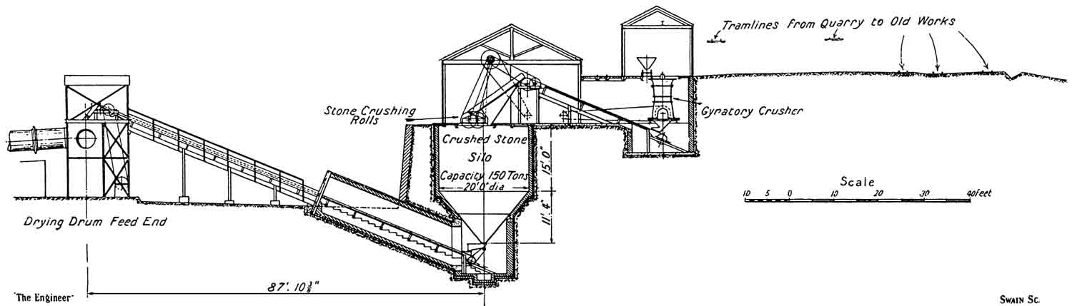
Fig. 2 - Section through crushing and drying plants. There are only two electric motors: one operating the gyratory crusher, and one operating the roll crusher and the intervening belt conveyor. The "percussion feeder" on the bin extraction in driven from the tail-drum of the conveyor to the dryer, which in turn is driven by the main engine via a rope drive, a lay-shaft and two belt drives. Evidently there was a static screen (not mentioned in the text) allowing the fines from the gyratory crusher to bypass the roll crusher. |
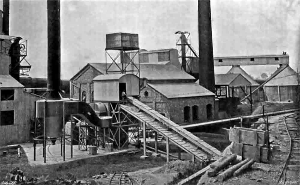
Fig. 7 - General view of the works. In the foreground is the inclined belt conveyor bringing crushed material from the underground bin extraction, feeding the dryer. Under the conveyor head is the fan drawing kiln gases through the dryer, and to the left is the cyclone with attached stack which takes the exhaust. The cyclone was intermittently emptied into a rail-mounted skip. No doubt, when dust started to billow from the stack, it was time to empty the cyclone. The dry raw material elevator is top left. Behind the conveyor (right) is the boiler house, with a raised header tank and brick stack, and (left) the engine house. Left of the stack is the clinker elevator, and the cement silos are on the right edge. |
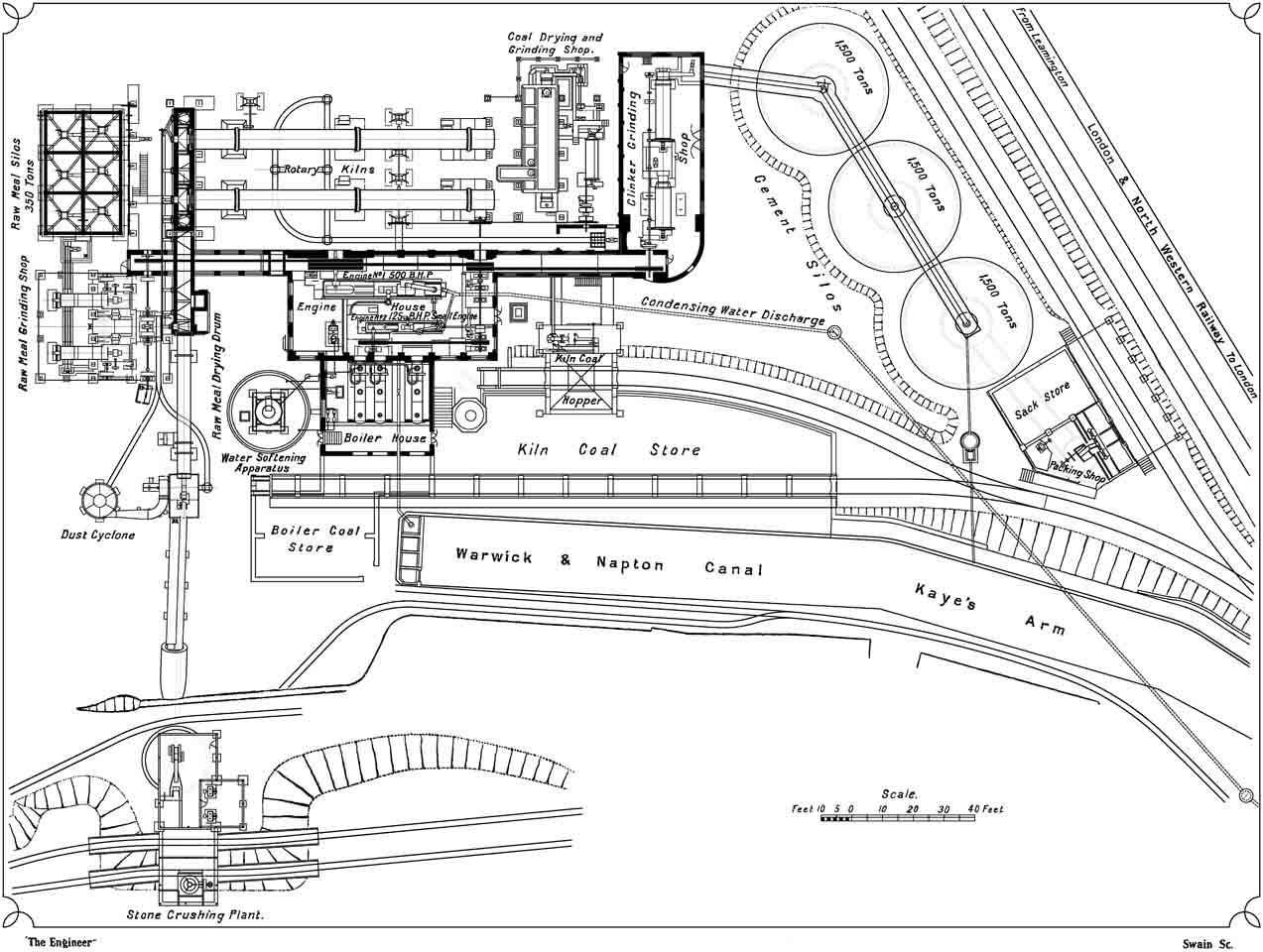
An examination of the accompanying engraving—Fig. 1 –which is a plan of the works, will aid the reader in following the raw material through the various stages until it becomes finished cement. The gases coming from the rotary kilns, to which we shall refer in due course, can either be sent up two riveted iron chimneys, immediately over their ends, or—as is ordinarily the case be diverted through the drying drum, thence passing through a Cyclone dust remover (Note 6), and away through a third riveted iron chimney. The drying drum is revolved by an ingenious arrangement of rope drive, the power being obtained from the shaft in the raw meal crushing shop. The crushed stone and clay are fed into the drum, which is arranged on an incline, and in their passage from one end to the other become thoroughly dried. Should it for any reason be desired not to divert the kiln gases through the drying drum, or for use when the kilns are not being worked, a stove has been provided in which the burning of coal will produce sufficient heat for the drying.
|
| Fig. 1 Plant Plan. View HD image in a new window. |
The drying drum discharges into a shoot delivering into a hopper. Into this hopper, we may add, the material collecting in the cyclone is also dropped, there being a special apparatus running on rails which is used for receiving the dust from the cyclone hopper and conveying it to the crushing shop. From the hopper in this shop the whole of the material is lifted by an elevator and delivered into two hoppers, shoots from which lead to the feeding tables of two Kominor grinders, which, in their turn, deliver into hoppers leading to two tube mills. These grinders are of the usual types, and require no special description. They receive their motion from a shaft which runs right through the building, and are all belt driven. It is this shaft which also works the drying drum, as already explained. The tube mills are on the ground level, the Kominor grinders being arranged on a raised platform supported on rolled steel joists.
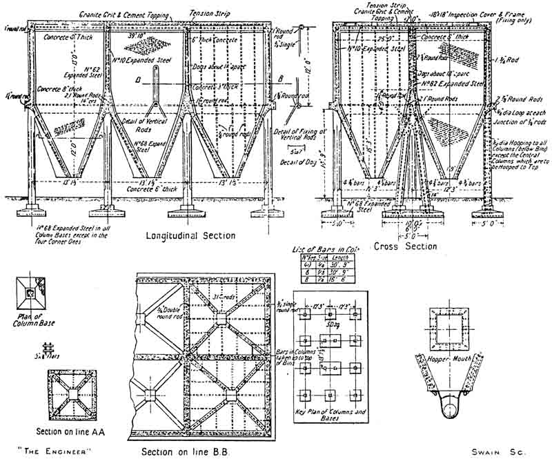
The raw meal, which is ground so as to leave only a residue of 5 per cent. on a 180 by 180 sieve (Note 7), is delivered into a horizontal worm conveyor which feeds a vertical elevator. The discharge from the latter is received into a further horizontal worm conveyor which runs over the tops of a battery of six armoured concrete bins (Note 8), which have been erected by the New Expanded Metal Company. These bins—see Figs. 3, 4, and Fig. 8—are carried on ferro-concrete uprights and supports, and are arranged in two rows of three each. The conveyor travels along the centre line dividing the two sets, and branch conveyors are led off to the centre of each bin. It is hence possible to feed any one of the bins as required. Each bin is provided at the bottom with a worm conveyor for withdrawing the raw meal. These conveyors deliver into another worm conveyor, which itself discharges into another conveyor. The latter feeds an elevator which raises the raw meal and delivers it into two hoppers above the kiln-charging platform (Note 9). The power to drive all this machinery is obtained by means of one single rope running off the main shafting. The subsidiary drives are carried out with belting. The raw meal bins have a capacity of some 350 tons, and they hold a store sufficient to enable the kilns to be kept at work during week-ends and other holidays when the raw meal grinding mills are not running.
 |
 |
| Fig. 3 - Details of raw meal silos. | Fig. 4 - Section though raw meal silos, kiln coal dryer, and cement silo. |
 | |
| Fig. 8 - Raw meal silos | |
The raw meal is now ready for charging into the kilns. It is withdrawn from either of the two hoppers just mentioned by a worm conveyor in each case. Each of these discharges into one end of a horizontal cast iron trough in which mixing knives revolve, these also acting as conveyors, forcing the meal from one end of the troughs to the other. One trough is fixed over the end of each kiln, and both are arranged on a ferro-concrete platform. Just as the meal enters the troughs there is a slight admixture of water, but this is only added in such quantity that the meal clings together in granules (Note 10). The discharge from each trough falls down a shoot into the charging end of its own kiln.
- o - O - o -
- Part 2 -
In the first article we traced the progress of the raw material through the works till it had been made ready for burning in the rotary kilns.
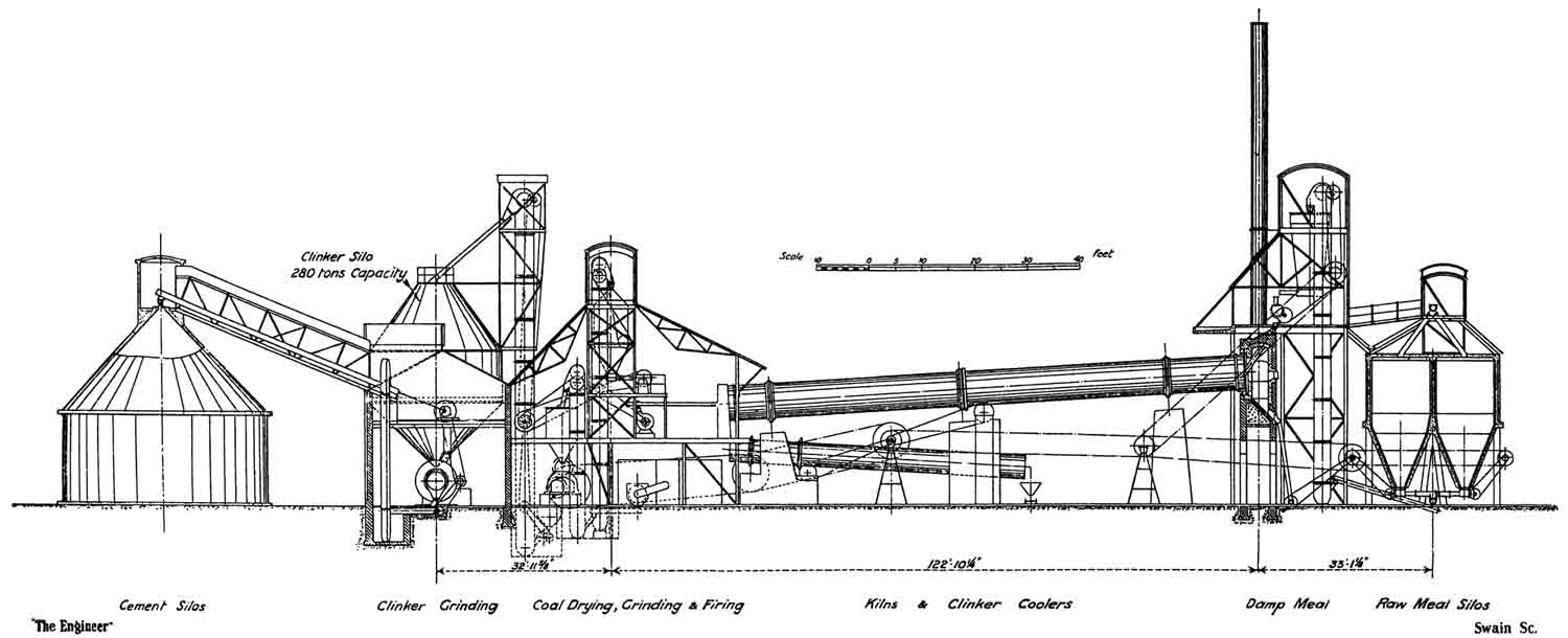
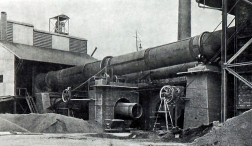
There are two kilns. They are 100ft. long and 7ft. diameter (Note 11), and they differ but little from the ordinary rotary kiln, of which we have described quite a number from time to time They are, however, made by a firm to which we have not hitherto referred in this connection, namely, Messrs. Fellner and Ziegler, of Frankfort. Each is driven by gearing through a toothed ring fixed as nearly as possible in the middle of its length, and there are three bearing rings, one in the middle and two near the ends, these each resting and revolving on four rollers carried in two pairs on hinged bearings. The motion of each kiln can be started, stopped, or regulated from the firing platform (Note 12), and the kilns themselves are driven from a cross shaft, which is in its turn driven by two ropes off the main driving shaft. Two views of the kilns are given in Figs. 13 and 14.
 |
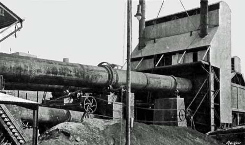 |
| Figure 13: Kilns - front end. The main drive shaft passes over the cooler between the first and second piers. From this, the kiln, cooler and feed elevator drives were operated by pulleys. The stack in the background is that of the power house. | Figure 14: Kilns - back end. The short, thin stacks provided all the draught when the dryer was by-passed. The raw meal bins are on the far right. |
The discharge from the kilns is into coolers, 40ft. long and 5ft. 6in. in diameter (Note 13). A motor-driven fan sucks air through the coolers and a portion of the hot air so obtained is used for drying the coal used for firing the kilns before it is ground. There are two centrifugal fans—one for each kiln—for forcing the powdered coal into the kilns, and the amount of coal so blown in is regulated by means of a throttling arrangement in the coal hopper, which delivers into a worm conveyor. The firing platform is made of ferro-concrete. The driving of the various pieces of apparatus is brought about by a shaft and belt, the former being driven by a large belt from a pulley at the ground level. The latter obtains its motion from the main drive, hereafter to be mentioned, through four ropes.
The hot gases, as they leave the kilns, usually, as already explained, pass through the raw material drying drum, but, when necessary, they can, by the alteration dampers, be diverted to iron chimneys, of which there is one for each kiln. A good deal of dust comes away from the kiln with the gases, and the majority of this is deposited in the flues, of which we give a drawing in Fig. 9 (Note 14). This dust is collected in various pockets, and as it falls from the outlets leading from these, it is collected by a conveyor and returned to the raw meal silos.
The clinker, as it comes from the cooler, is very slightly moistened by slowly dripping jets of water. It is practically quite cold; indeed, we do not remember having noticed clinker from any of the other rotary kilns which we have inspected which was as cold. It is also excellently burnt, and is in exceptionally small pieces. The following has been given as a typical analysis of the cement produced. The analysis was, we understand, made by Messrs. H. Faija and Co., of Westminster.
| Analysis of Kaye and Co.'s Cement | |
| Water & carbonic anhydride | 1.24 |
| Insoluble Residue | 0.13 |
| Silica | 20.20 |
| Alumina | 8.68 |
| Oxide of iron | 3.40 |
| Lime | 62.74 |
| Magnesia | 1.23 |
| Sulphuric anhydride | 1.17 |
| Alkalies and loss | 1.21 |
| 100.00 | |
There are one or two points worthy of notice about this analysis. They relate to the requirements of the British Standard Specification. In this it is set out that the water and carbonic anhydride must not exceed 2 per cent.; compare this with 1.24 per cent. above. The insoluble residue permissible is 1.5 per cent , whereas in Kaye's cement it is only 0.18 per cent. Magnesia must not exceed 3 per cent., and the Kaye's cement only contains 1.23 per cent., while up to 2.75 per cent. of sulphuric anhydride is allowed, and, as will be seen from the above analysis, only 1.17 per cent. is actually present (Note 15). While on the subject of the cement it will, perhaps, be of interest to give a copy of a series of results of physical tests made by the above-mentioned firm.
| Results of Tests Made at Twenty-eight Days | |||||
| Nature of test | 1 | 2 | 3 | 4 | Requirement |
|---|---|---|---|---|---|
| of British | |||||
| Standard | |||||
| Specification | |||||
| Expansion | Nil | 1 mm | 1 mm | 1 mm | 10 mm |
| Le Chatelier Test | |||||
| Neat cement | 770 lb | 857 lb | 805 lb | 762 lb | 500 lb |
| 3 to 1 sand | 499 lb | 571 lb | 552 lb | 499 lb | 250 lb |
| MPa (Note 16) | 25 | 30 | 29 | 25 | |
| Residue 76×76 sieve | 1 % | 0.5 % | 1 % | 0.5 % | 3 % |
| Residue 180×180 sieve | 12 % | 10 % | 11 % | 10 % | 18 % |
It will be observed that in all cases the results obtained were better than the requirements of the British Standard Specification. We may add that we broke some briquettes ourselves and obtained some results which were practically in accordance with those set out above. We also saw a large number of Le Chatellier (sic) cylinders, and in the majority of cases these showed no expansion at all (Note 17).
The clinker as it issues from the coolers falls into tip wagons which run on rails. These, when full (Note 18), are wheeled away by hand, and the clinker shot through a grid into the hopper of an elevator. It is then lifted and discharged into a hopper capable of holding some 280 to 300 tons, being made of large capacity so as to take the make of clinker at week ends and other times when the grinding plant is not at work. This is constructed of ¼in., and 3/16 in. steel plates. The discharge from the bottom of this hopper is through an automatic feed through which the proper quantity of clinker is regularly delivered to the first of two tube mills made by Krupp. The discharge from the first tube mill is taken up an elevator and discharged into the second mill. Each of the mills revolves on two sets of rollers, and is driven by gearing which is actuated by belting from a main cross shaft, which in its turn obtains its motion from the main drive by means of ropes. The cement as it issues from the second tube mill is in a completed state (Note 19). It is at once elevated by a vertical elevator and delivered into the hopper of an inclined conveyor which lifts it to the top of the first of three large storage bins or silos, the tops of which are connected by means of a covered gallery, along which runs a horizontal worm conveyor. so that the cement can be delivered into either or all the bins as required. These bins are constructed of ferro-concrete on the Hennebique principle. We give a sectional drawing of them in Fig. 12 and a general view in Fig. 15. They are conical in shape, both top and bottom, with a parallel portion between them, and each holds 1500 tons. The bottom cones descend into a ferro-concrete tunnel, along which runs a horizontal worm conveyor. Into this the bins can be discharged either separately or together through other worm conveyors, of which one is fitted to each bin. The main conveyor delivers into the hopper of another worm conveyor which leads the cement to an elevator, which, in its turn lifts it and discharges it into shoots for filling sacks. Four sacks can be filled at one time. The conveying and elevating machinery in connection with the discharge from the bins is driven by a 25 horse-power Thomas Parker and Co.'s dynamo (sic), through a single rope.
The Cement Silos | |
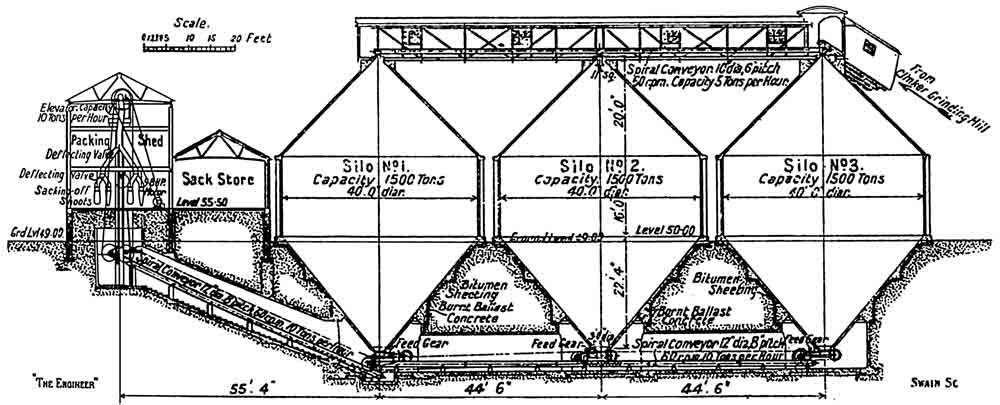 Fig. 12 - Section through cement silos. Three extraction screws, two screw conveyors and the elevator are all driven by one electric motor. Packers for sacks of predetermined weight were not available at this time. Sacks (made of jute) were strapped to the discharge point, a slide was withdrawn, and cement ran in until the sack was "full". The four packing spouts were close to the rail dock, and sacks were loaded directly into rail wagons. The silos were extraordinarily large by the standards of the day. Each silo had effective volume 1003 m3. Although the concrete is thin, these silos stood for many years, and one must assume they were structurally sound. Fig. 12 - Section through cement silos. Three extraction screws, two screw conveyors and the elevator are all driven by one electric motor. Packers for sacks of predetermined weight were not available at this time. Sacks (made of jute) were strapped to the discharge point, a slide was withdrawn, and cement ran in until the sack was "full". The four packing spouts were close to the rail dock, and sacks were loaded directly into rail wagons. The silos were extraordinarily large by the standards of the day. Each silo had effective volume 1003 m3. Although the concrete is thin, these silos stood for many years, and one must assume they were structurally sound. |
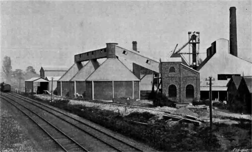 Figure 15: View from the west. Left of the cement silos is the packer with its awning over the rail dock. To the right is the end of the brick-built finish mill house, with the clinker elevator and conical clinker bin in the background. Figure 15: View from the west. Left of the cement silos is the packer with its awning over the rail dock. To the right is the end of the brick-built finish mill house, with the clinker elevator and conical clinker bin in the background. |
Returning now for a moment to the coal used for firing the kilns. The coal coming into the works by rail or canal is shot into a large hopper. At the bottom of this works a conveyor which delivers the coal to a bucket elevator. This lifts it to a conveyor arranged at the firing platform level, which takes it to a shoot above a tube drier, down to which it falls through a shoot. The drier is heated by the hot air drawn through the clinker coolers as already mentioned, and there is a subsidiary stove for use if necessary. The discharge from the drier is into a worm conveyor, which itself discharges into another at right angles. This in turn delivers into an elevator which lifts the coal into the hopper of the first of two tube grinding mills. The coal after passing through both these mills is in a sufficiently fine state for use. The discharge from the second mill is fed into an elevator through an automatic feeding arrangement. The elevator lifts the powdered coal into storage bins above the firing platform level. The mills are driven by gearing from a cross shaft.
The motive power for the whole works is obtained by means of two steam engines, one of 540 brake horse-power—see Fig.16, and the other of 125 brake horse-power. Both are horizontal tandem compound engines, made by Pollitt and Wigzell, and both work condensing, jet condensers being fitted. The condensing water is obtained from the canal close by, and the heated water after passing through the condenser is not returned directly into the canal but is led away some distance through the pipe shown on the engraving—Fig. 1 (ante)-and discharged into the canal at point where the level of the latter is lower. This arrangement has the advantage of keeping the condensing water much cooler than it would otherwise be. The feed-water is also taken from the canal, but it is exceedingly hard, and had to be softened in the apparatus shown beside the boiler-house. There are three Babcock and Wilcox boilers fitted with Bennis stokers. They work at 150 lb. per square inch, and are each capable of evaporating 5500 lb. of water per hour.
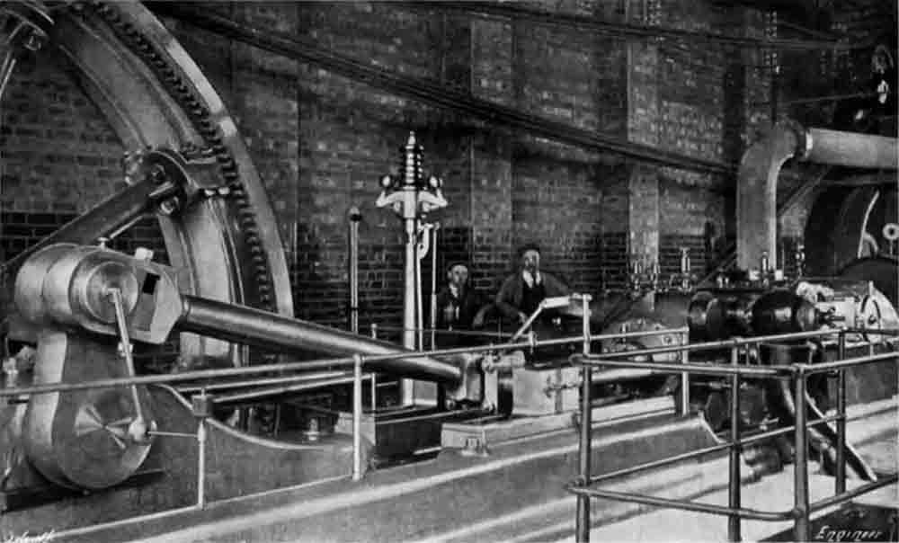 Figure 16: The main engine. The drive ropes powering the kilns and finish mills run off the flywheel to the right. The ropes for the rawmills run off to the left. Figure 16: The main engine. The drive ropes powering the kilns and finish mills run off the flywheel to the right. The ropes for the rawmills run off to the left. |
The main engine is provided with a large fly-wheel grooved for rope driving, and ropes are run in either direction in a rope race formed between the engine-house and the kiln house. In one direction these ropes actuate the shafting of the raw meal grinding shop; in the other the kilns and the remainder of the machinery in the works. The smaller engine can work in parallel with the main engine by means of a clutch on a countershaft (Note 20). There are two dynamos in the engine-house. One of these has an output of 410 ampères by 220 volts, and is driven off the shafting. It is this machine which provides the current for working the various motors which have been mentioned in the foregoing. The second dynamo has an output of 80 ampères by 220 volts. It is coupled direct to a separate vertical steam engine, and is used for lighting and also for power purposes when the main engines are not running.
The works, as a whole, are exceedingly well arranged. Every advantage has been taken both of the configuration of the ground and of the railway and canal. There are three branches of the railway siding running into the works. One of these goes past the cement despatching shed, in which are the sack-filling arrangements above referred to. Another runs right over the kiln coal hopper, so that wagons can be emptied direct into it. while the third siding is taken along behind the boilers to a coal store, which is situated at the termination of the arm of canal. This siding had to be well above ground level, and it was decided to carry it on a series of ferro-concrete piers. These were erected by the company itself, and constitute an excellent piece of work. It will have been observed that considerable use had been made of ferro-concrete in these works. We understand that in one case, at all events, the comparative cost of steel and ferro-concrete was gone into very carefully, and it was found that for the same strength the latter was actually the cheaper.
A description of these works would be incomplete without a reference to the chemical and physical testing laboratories. Both of these are well equipped and managed, and work in them is being continuously carried out. We are enabled to give views of them in Figs. 10 and 11.
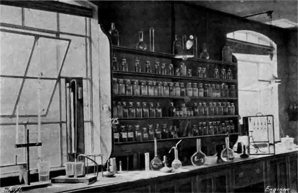 Figure 10: The chemical laboratory. On the left is a calcimeter for calcium carbonate determination; on the right is an Orsat gas analyser for analysing kiln exhaust gas. Figure 10: The chemical laboratory. On the left is a calcimeter for calcium carbonate determination; on the right is an Orsat gas analyser for analysing kiln exhaust gas. |
 Figure 11: The physical laboratory. To the left is an Adie tensile strength apparatus; on the bench to the right of it is a Michele tensile strength apparatus. Figure 11: The physical laboratory. To the left is an Adie tensile strength apparatus; on the bench to the right of it is a Michele tensile strength apparatus. |