
1940s Tunnel Brand

Tunnel White Brand

Big T Brand used from the late 1960s
Location:
- Grid reference: TQ57737798
- x=557729
- y=177981
- 51°28'44"N; 0°16'17"E
- Civil Parish: West Thurrock, Essex
Clinker manufacture operational: 1874 to 1976
Approximate total clinker production: 41 million tonnes (9th)
Raw materials:
- Upper Chalk (Seaford Chalk Formation: 85-88 Ma) from a 1.2 km face progressively pushed eastwards from the plant, eventually reaching a distance of 1.2 km from the plant. During the 1960s, a further quarry was opened at 558000,179600 to the north of the A1306.
- Alluvial Clay initially by barge from Canvey Island: from 1927, London Clay (London Clay Formation: 48-55 Ma) slurry from Aveley at 555700,180400: washmill at 555610,180110.
Ownership:
- 1874-1968 Tunnel Portland Cement Company Ltd
- 1968-1976 Tunnel Cement Ltd
Despite the supreme importance of this site, I have had great difficulty in getting reliable data, and history of the kilns in particular is still work-in-progress. Until I obtained aerial photographs, information on the kilns was almost non-existent, and what little I know is based largely on them. Please contact me with any relevant information and corrections.
Alternatively called Tunnel Works, this was the parent plant of the Tunnel company, and was named after Tunnel Farm, on the lands of which it was situated, and which had been so named since the mid 18th century at least. The plant started with six wet process bottle kilns, increasing to twelve (330 t/week) by 1885, at which time a set of six chamber kilns were built (150 t/week). A further set of eight (250 t/week) were built in the mid 1890s, and the bottle kilns were abandoned, leaving the output at 400 t/week, which it remained in 1907. In 1911, sale of the company to F. L. Smidth was completed. This marked the start of the FLS involvement in British and Irish production with holdings ultimately in Tunnel, Ketton, Ribblesdale and Cement Limited (Irish Cement). The immediate investment was rapid and transformed West Thurrock from an insignificant site into the largest British plant within a few decades. Blount (pp 91-95) gives an account of the plant as reconstructed. Read this account.
The old plant was completely cleared, and rotary kilns were installed. These were not FLS’s largest: larger kilns had been supplied as Wouldham A9 and Penarth B1. The plant then grew organically over the next fifty years, with nine distinct stages of up-rating – more than any other site. The result, by the end of the process, was a decidedly chaotic plant layout. As an FLS showcase, a number of pioneering plant designs were incorporated.
A3 was the first “Unax” kiln with planetary coolers (read the Engineer article describing this), while A4 was the first to be fitted with a modern chain system – an innovation that was rapidly emulated by the other companies after intelligence regarding the technique leaked out. The installation of A6 in 1934 transformed the status of the plant: it was easily the largest kiln in the country and remained so until 1961 (when it was overtaken by B1 and then by Westbury A1). From 1934 until Pitstone took over in 1957, white cement was made. An asbestos-cement plant, owned by Tunnel Asbestos Cement Co. Ltd, was established in 1936, in the quarry to the north of the kilns.
The plant was substantially damaged during WWII, and seems to be unique among UK plants in having been specifically targeted for bombing - at other places damage was random and accidental. In the post-war period, up-rating consisted of installation of kiln A8, and replacement of the old, small kilns 1-3 and the now unreliable kiln 6. B1 from 1962 became Britain’s largest kiln, until exceeded in size by Westbury A1 later that year. In overall capacity, the plant became the largest in the UK (overtaking Johnsons) with the installation of kiln 6 in 1934. It remained the largest plant until 1971, when it was overtaken by Northfleet.
The plant had run on oil from 1958, and the newer kilns had been installed without coal firing facilities. With the post-1973 rise in energy prices and market downturn, the future of the site was re-assessed. The plant had easily the highest manufacturing costs in the group, and at the increased capacity, chalk reserves were rapidly disappearing. The Essex bank outcrop is narrow, and the northward growth of Grays had cut off the quarry’s eastward development. Downward extension was limited by the water table and salt ingress. With the installation of more efficient kilns at Padeswood, Pitstone, Ketton and Ribblesdale, the brave decision was made to close the site altogether.
The site had a rail link from the outset although it always used a barge wharf to which it was joined by a 2 km standard gauge railway. A separate deep-water jetty was installed 300 m upstream in the 1930s. In line with early FLS philosophy, materials were moved around by rail rather than conveyors, and with its development in 1920-1940 it became a maze of rail track, boasting at its peak 20 km of private track. The jetty remained in use for receipt of fuel. The site was rapidly redeveloped and is now covered with light industry and warehousing. The jetty is used by an oil and chemicals transporting operation. The main chalk quarry is now the Lakeside Retail Park.
Please contact me with any relevant information or corrections. I am particularly interested in firmer dates and statistics.
Power Supply
The early plant was directly driven by steam engines. The new plant of 1912 was entirely electric powered from a central power house equipped with turbo-generators, plus a backup generator driven by a gas engine. From 1929, the plant used purchased power from Barking, the power house remaining as a back-up.
Rawmills
Washmills were always used. With the installation of rotary kilns, washmills, in closed circuit with centrifugal screeners, were installed immediately to the west of the kiln house. The screened slurry was further ground in a tube mill. These were extended in a row parallel to the kilns until the installation of Kiln 7, when there was no further room. A completely new washmill installation was then constructed in the quarry to the northeast of the kilns, and was extended as necessary with the post-war capacity increases.
Twelve distinct rotary kilns were installed in nine stages:
Kiln A1
Supplier: FLS
Operated: 29/03/1913 -1947
Process: Wet
Location: Hot end 557686,177923: Cold end 557689,177985: entirely enclosed.
Dimensions: metric 62.10 × 2.700B / 2.400CD
Rotation (viewed from firing end): anti-clockwise.
Slope: 1/25 (2.292°)
Speed: ?
Drive: ?
Kiln profile: 0×2400: 3000×2400: 3000×2700: 10500×2700: 12000×2400: 62100×2400: tyres at 1500, 13500, 25200, 39600, 56400: turning gear at 22800.
Cooler: pressurised “double-back” concentric rotary metric 11.25 × 1.500 / 1.350 / 2.100 beneath the kiln
Cooler profile: 0×1500: 4200×1500: 4200×1350: 10800×1350: 11250×2100: 4500×2100: tyre at 2850 with trunnion end bearing: turning gear at tail end.
Fuel: Coal
Coal Mill: indirect: FLS ball and tube mill shared by kilns 1 & 2
Exhaust: via dry drop-out chamber direct to stack.
Typical Output: 1912-1930 150 t/d: 1930-1947 200 t/d
Typical Heat Consumption: 1912-1930 7.89 MJ/kg: 1930-1947 7.49 MJ/kg
Kiln A2
Operated: ?25/10/1913 -1947
Location: Hot end 557694,177923: Cold end 557697,177985: entirely enclosed.
Identical in all other respects to A1.
Kiln A3
Supplier: FLS
Operated: 18/12/1923 -1951?
Process: Wet
Location: Hot end 557704,177914: Cold end 557707,177977: entirely enclosed.
Dimensions: Metric (from cooler ports) 63.00 × 2.700B / 2.400CD
Rotation (viewed from firing end): ?
Slope: 1/25 (2.292°)
Speed: ?
Drive: ?
Kiln profile (from cooler ports): -2000×2700: 20000×2700: 22400×2400: 63000×2400: tyres at 2200, 14100, 29100, 44100, 56100: turning gear at 26700 ?
Cooler: Unax planetary 12 × 5.40 × 0.600
Fuel: Coal: Oil on white
Coal Mill: indirect: ?
Exhaust: via dry drop-out chamber direct to stack.
Typical Output: 1923-1930 165 t/d: 1930-1933 225 t/d: 1934-1939, 1946-1951 (white) 163 t/d
Typical Heat Consumption: 1923-1930 8.36 MJ/kg: 1930-1933 7.88 MJ/kg: 1934-1939, 1946-1951 (white) 9.88 MJ/kg
Kiln A4
Supplier: FLS
Operated: 23/03/1929 - early 1971
Process: Wet
Location: Hot end 557715,177932: Cold end 557719,178024: hot end enclosed.
Dimensions: Metric (from cooler ports) 92.10 × 3.000B / 2.400CD
Rotation (viewed from firing end): clockwise
Slope: 1/25 (2.292°)
Speed: ?
Drive: ?
Kiln profile (from cooler ports): -2200×3000: 25000×3000: 27400×2400: 92100×2400: tyres at 2200, 13600, 29000, 46200, 65400, 89100: turning gear at 31700 ?
Cooler: Unax planetary 12 × 6.00 × 1.250
Fuel: 1929-1958 Coal: 1958-1971 Oil
Coal Mill: indirect: ?
Exhaust: via ID fan direct to stack. An electrostatic precipitator was added after the fan around 1950.
Typical Output: 290 t/d
Typical Heat Consumption: 7.33 MJ/kg
Kiln A5
Operated: 08/05/1931-early 1971
Location: Hot end 557723,177931: Cold end 557728,178023: hot end enclosed.
Identical in all other respects to A4
Kiln A6
Supplier: FLS
Operated: 15/10/1934-1960
Process: Wet
Location: Hot end 557729,177895: Cold end 557736,178045: hot end enclosed.
Dimensions: (from cooler ports) metric 150.00 × 3.750B / 3.450C / 3.900D
Rotation (viewed from firing end): clockwise.
Slope: 1/25 (2.292°)
Speed: ?
Drive: ?
Kiln profile (from cooler ports): -3500×3750: 32600×3750: 36000×3450: 105000×3450: 108500×3900: 150000×3900: tyres at 2500, 21500, 41250, 61000, 81250, 102000, 121500, 143000: turning gear at 44700 ?
Cooler: Unax planetary 12 × 7.75 × 1.200
Fuel: 1934-1958 Coal: 1958-1960 Oil
Coal Mill: indirect: ?
Exhaust: via ID fan direct to stack. A pair of parallel electrostatic precipitators was added after the fan around 1938.
Typical Output: 1934-1941 815 t/d: 1945-1960 790 t/d
Typical Heat Consumption: 7.05 MJ/kg
Kiln A7
Supplier: FLS
Operated: 18/06/1937 -01/04/1975
Process: Wet
Location: Hot end 557773,177928: Cold end 557778,178057: hot end enclosed.
Dimensions: Metric (from cooler ports) 129.00 × 3.600B / 3.300C / 3.600D
Rotation (viewed from firing end): ?
Slope: ?
Speed: ?
Drive: ?
Kiln profile (from cooler ports) : -3300×3600, 43000×3600, 45000×3300, 95000×3300, 97000×3600, 127700×3600, 127700×3150, 129000×3150: tyres at 4000, 17500, 36750, 57750, 79500, 100250, 122000: turning gear at 54450: dust scoops at 92500 ?
Cooler: Unax planetary 12 × 6.00 × 1.250
Fuel: 1938-1958 Coal: 1958-1971 Oil: 1971-1975 Gas
Coal Mill: indirect: ?
Exhaust: via ID fan to a pair of parallel electrostatic precipitators. A further precipitator in series seems to have been added around 1970.
Typical Output: 1938-1971 650 t/d: 1971-1975 620 t/d
Typical Heat Consumption: 7.10 MJ/kg
Kiln A8
Supplier: FLS
Operated: 1959q2 -01/04/1976
Process: Wet
Location: Hot end 557785,177921: Cold end 557791,178057: hot end enclosed.
Dimensions: Metric 135.60 × 3.600BC / 3.950D
Rotation (viewed from firing end): ?
Slope: ?
Speed: ?
Drive: ?
Kiln profile: 0×3600, 86000×3600, 89000×3950, 135600×3950: tyres at 10000, 31000, 53000, 77000, 101350, 125400: turning gear at 73400: dust scoops at 91000 ?
Cooler: Folax ?836 grate.
Fuel: 1959-1971 Oil: 1971-1976 Gas
Exhaust: via ID fan to a pair of parallel electrostatic precipitators.
Typical Output: 1959-1971 770 t/d: 1971-1976 730 t/d
Typical Heat Consumption: 7.01 MJ/kg
Kiln B1 (called 1a)
Supplier: FLS
Operated: 1962-01/04/1975
Process: Wet
Location: Hot end 557684,177919: Cold end 557691,178071: hot end enclosed.
Dimensions: Metric (from cooler ports) 151.75 × 3.600BC / 3.950D
Rotation (viewed from firing end): ?
Slope: ?
Speed: ?
Drive: ?
Kiln profile (from cooler ports): -3300×3600, 105000×3600, 107000×3950, 151750×3950: tyres at 4000, 37500, 75000, 112500, 140000: turning gear at 71400: dust scoops at 103000 ?
Cooler: Unax planetary 10 × 10.80 × 1.350
Fuel: 1962-1971 Oil: 1971-1975 Gas
Exhaust: via ID fan to a pair of parallel electrostatic precipitators.
Typical Output: 1962-1971 840 t/d: 1971-1975 800 t/d
Typical Heat Consumption: 6.98 MJ/kg
Kiln B2 (called 2a)
Supplier: FLS
Operated: 01/02/1949-1/1975
Process: Wet
Location: Hot end 557695,177947: Cold end 557699,178037: hot end enclosed.
Dimensions: Metric 90.00 × 3.000BC / 3.450D
Rotation (viewed from firing end): ?
Slope: ?
Speed: ?
Drive: ?
Kiln profile: 0×3000, 63000×3000, 65000×3450, 89250×3450 89250×3000: 90000×3000: tyres at 10000, 30000, 52000, 78500: turning gear at 49000: dust scoops at 55500 ?
Cooler: Folax ?624 grate.
Fuel: 1950-1958 Coal: 1958-1971 Oil: 1971-1975 Gas
Coal Mill: indirect: ?
Exhaust: via ID fan to an electrostatic precipitator.
Typical Output: 1950-1971 390 t/d: 1971-1975 370 t/d
Typical Heat Consumption: 7.07 MJ/kg
Kiln B3 (called 3a)
Operated: 12/1952 -1/1975
Location: Hot end 557706,177947: Cold end 557710,178037: hot end enclosed.
Identical in all other respects to B2
Kiln B6 (called 6a)
Supplier: FLS
Operated: 1961-1/4/1975
Process: Wet
Location: Hot end 557729,177894: Cold end 557736,178045: hot end enclosed.
Dimensions: Metric (from cooler ports) 151.25 × 3.600B / 3.450CD
Rotation (viewed from firing end): clockwise.
Slope: 1/25 (2.292°)
Speed: ?
Drive: ?
Kiln profile (from cooler ports): -3500×3600: 32600×3600: 36000×3450: 151250×3450: Tyres at 3250, 31250, 59250, 82500, 103250, 122750, 144250: turning gear at 78500 ?
Cooler: Unax planetary 10 × 10.80 × 1.350
Fuel: 1961-1971 Oil: 1971-1975 Gas
Exhaust: via ID fan to two parallel electrostatic precipitators.
Typical Output: 1961-1971 785 t/d: 1971-1975 745 t/d
Typical Heat Consumption: 7.02 MJ/kg
Sources:
- Primary Sources:
- Tunnel Cement (brochure), Tunnel Portland Cement Co., Ltd., 1950
- Blount, pp 91-95 (Read this.)
- Victoria County History of Essex, II, p 493
- Ordnance Survey 1:2500 mapping
- BGS mapping and monographs
- "A combined rotary cement kiln and clinker cooler", The Engineer, CXL, p 124 (read this)
- Confirmatory Sources:
The following is a transcript of an article that first appeared in the Times Engineering Supplement, and was quoted by Bertram Blount in his 1920 book.
It describes the renovated West Thurrock plant in its original form, as completed in 1914.
The plant had its origin as an unremarkable plant with batch kilns, which remained small compared with other plants on the Essex bank of the Thames Estuary. Unlike the others, it did not join the "Combine" in 1900 - the promoters seem to have regarded it as too insignificant to be worth pursuing. However, their mistake soon became apparent when F. L. Smidth bought the plant in 1911, and reconstructed it as a showcase for their equipment. FLS had other showcase plants, the most obvious being Aalborg in Denmark. After WWI, West Thurrock was continually extended with the latest FLS equipment, and by the mid-1930s, it was the biggest British plant. It was finally closed in 1976, due to the high energy penalty of using the wet chalk of the Southeast for cement manufacture.
Bertram Blount quoted the Times Engineering Supplement article as an example of a modern wet process plant of the time. He says:
"To consolidate the reader's ideas it may be useful to print a description of typical works. The first is an excellent example of a modern works built by Messrs. Smidth on the site of an old works with fixed kilns. The raw materials are those usual in the district, consisting of chalk and clay of the usual good quality used at Thames and Medway works. A description of the works, taken from the Times Engineering Supplement, is appended. The writer knows the works and accepts the description as correct."
It is a matter of common knowledge that the Portland cement industry in this country has been passing through seasons of great vicissitude, and that during the past few years it has become necessary for much of the old plant to be consigned to the scrap-heap. It is scarcely too much to say that in the short space of a decade the whole process of manufacture has been revolutionised, and that many works thought to be efficient and up-to-date at the close of last century have been proved to be completely obsolete and incapable of being conducted at a profit.
A change of this character has taken place at West Thurrock in the works of the Tunnel Cement Company, originally erected in 1874, which have now been reconstructed and equipped with entirely new plant by Messrs. F. L. Smidth and Co., of Copenhagen. The original works, kilns and all, have disappeared and the only trace of the old buildings is a part of the former ware-house. The works may be now looked upon as being typical of the modern methods introduced into this branch of manufacture. The most remarkable feature is the great length of the rotary kiln (Note 1) and the extreme uniformity of the quality of the cement, consequent upon the employment of single units of the largest size.
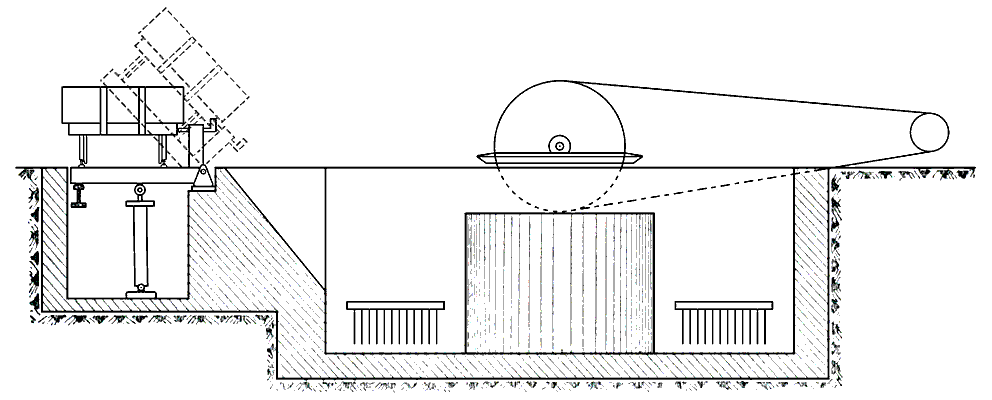 Fig. 47 Fig. 47 |
WASH MILL
The chalk, brought in trucks from a neighbouring quarry, and the clay, also loaded in trucks are conveyed to the edge of the wash mill, and after being weighed are tipped by hydraulic pressure, in truckloads at a time, into the wash mill (shown in Fig. 47), capable of dealing with 50 tons of raw material an hour. The chalk and clay are reduced to slip or "slurry" by revolving stirrers of the drag-harrow type, and the slip is pumped up to the separators, where the coarse particles are removed. This is effected by centrifugal wringers (Note 2), the sides of which are lined with wire gauze that permits the fine particles in suspension to pass through, but retains the coarser matters for return to the wash mill. The roughly screened slurry, after being further ground in a tube mill, is run into a series of tanks, provided with stirrers in order to prevent deposition, after which it is lifted by a pump to the top of the kiln building. This is a fine hall, about 240 ft. in length by 55 ft. in width, containing two rotary kilns with clinker-cooling cylinders and coal-grinding plant. A photograph is given (Fig. 48).
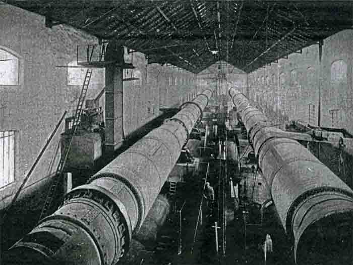 Fig. 48 Fig. 48 |
ROTARY KILN
Each rotary kiln, into the upper end of which the slurry is introduced at the rate of about 45 gallons a minute (Note 3), is inclined at an angle of 1 in 25 with the horizontal and is supported on five sets of friction rollers. Each kiln, which is 210 ft. in length by 8 ft. in diameter, increased to 9 ft. near the firing end (Note 4), is driven by powerful gearing at the centre and revolves at the rate of one complete turn in 65 sec. It consists of a tube, formed of mild steel plates riveted together, and lined throughout with firebrick. The fuel, which is Newcastle coal ground to a fine powder (about 15 % residuum on the 180-mesh sieve), is blown into the kiln by a high-pressure fan, and the air needed for combustion, previously heated by being passed over the red-hot clinker quitting the kiln, is also blown in by a fan (Note 5). This kiln, when in normal work, is capable of yielding 7½ tons of clinker an hour, with a fuel consumption equal to 28 % of the weight of the cement. The coal is ground in a 'kominor', or ball mill, and is finished in a tube mill, whence it is raised into a feeding hopper.
GRINDING PLANT
The clinker, as it issues from the cooling cylinder, placed beneath the rotary kiln, is lifted by a conveyor into a storage-hopper, whence it is removed in iron trucks and wheeled by hand on a narrow-gauge railway to the mill house (Note 6). The kominor into which it is tipped along with a measured quantity of gypsum, to delay the setting time of the cement, will turn out 10 tons of finely crushed clinker an hour, and the ground material from the kominor is conveyed to the tube mill, 6 ft. 6 in. in diameter and 24 ft. in length, in which the cement is ground to an extremely fine powder. The specified fineness of grinding is 12 % residue on the 180-mesh sieve. The ground cement issuing from the tube mill is transferred by a spiral screw conveyor to an endless rubber belt, 170 ft. in length, leading to the silos, six in number, 30 ft. in diameter and 50 ft. in height, with a united capacity of 10,000 tons of cement.
AUTOMATIC SACK FILLING
The use of the "Exilor" machines for sack filling constitutes a marked improvement on the old-fashioned plan of working. The empty sack, attached by clips to the orifice of a tube leading from the silo, is shut into an airtight chamber, formed in two sections, and in the act of closing the door an air-exhaust is started. Owing to the vacuum created a stream of cement from the silo is drawn through the tube into the sack. The sack is hung at one extremity of the beam of a weighing machine, in the scale-pan of which is the exact weight of a filled sack. In 10 or 12 seconds the requisite quantity of cement has been drawn into the sack, which then tilts the beam, thereby opening the air-valve : this breaks the vacuum and stops the flow of cement. The opening of the door to remove the sack enables a small fan to carry away the dust from the mouth of the sack and the door is ready to be swung back and closed against the other chamber of the Exilor, in which another sack has in the meantime been fixed in readiness for filling. The door is hinged on the centre line, so as to be capable of being closed against each section of the chamber in turn. A gang of three expert work-men fill and wheel away 120 sacks of cement in the hour, with the precise weight required in every sack. A small air pump, driven by motor, is all the power needed to convey the cement from the silo into the sack, and the vacuum created is about 15 in. of mercury.
POWER HOUSE
The power throughout the works is generated electrically and is conveyed by cables to the various machines. The power-house is a handsome building (Note 7), containing ample space for additional plant. At present a steam turbine driving a powerful dynamo, furnishing three-phase current at 50 periods per second, is the main source of supply, but there is a 250 h.p. gas-engine to serve as a stand-by. The total weight of the turbine and dynamo is 27 tons, whereas the fly-wheel alone of a reciprocating engine to furnish the same amount of power was estimated to weigh over 50 tons. Steam is supplied by two Steinmüller boilers, each of 1000 h.p., with chain grate stokers.