Early kilns used for cement burning were “static”, either batch-process kilns based upon the primitive egg-cup shaped traditional lime kiln, or later, “shaft” kilns which operate continuously.
One frequently encounters references to open lime kilns being operated continuously, with periodic withdrawal of small amounts of product, and topping up with raw material and fuel. This was never the case when burning cement, mainly due to the formation of a rigid mass of sintered material in the kiln that would not flow readily. Kilns were, however, sometimes “topped up” as the burning charge shrank in the kiln, allowing an increased output, at the expense of a more variable product.
Bottle kilns
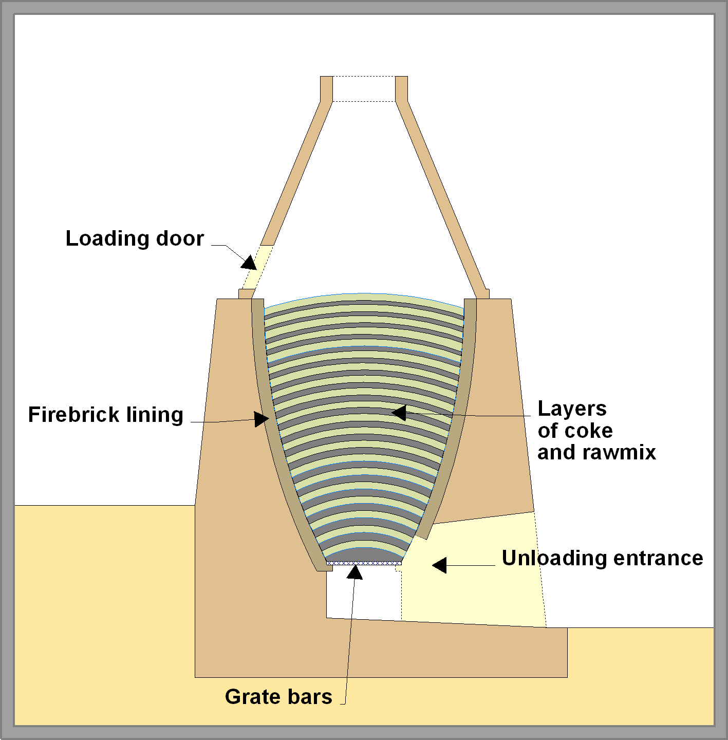
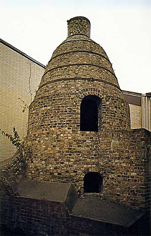
The original format was the “bottle kiln” (sometimes called "closed kiln" or "dome kiln") - a hybrid of the traditional open lime kiln and the bottle kiln of the ceramics industry: a light brickwork structure was built upward from the lime kiln hearth, either in conical form or in bottle-top ("beehive") form, the idea being to form a chimney of sufficient height to considerably increase the natural draught produced. Static kilns must be fed with fairly hard, fairly large and uniform-sized lumps of material. This is to allow combustion air to pass freely though the whole of the charge, and to avoid collapse (and consequent smothering) of the charge during burning. An open-structured charge is also vital after the burning stage, since poor air-flow leads to a slow cooling stage, adversely affecting output, and causes “dusting” of the clinker as a result of β-γ inversion of the belite. Because of highly disciplined manufacturing techniques and understanding of the chemistry, this phenomenon is today rarely encountered, but in the early industry it was common, and was fatal to many early attempts to make the product.
The early kilns differed little in size and output, because of the mechanical properties of the raw material. Kilns were hemi-spheroidal (i.e. egg-cup shaped), with diameter typically 10-18 feet, and depth somewhat greater than the diameter. Very occasionally kilns over twenty feet in diameter are encountered, but these are rare. Rawmix in lump form was heaped into the kiln in domed layers, and in order to avoid collapse of the charge, the layers needed to maintain their shape throughout the burning process. The weakness of this self-supporting structure limited the diameter that could be spanned. Kilns of larger diameter could therefore not be filled to their full depth, and output was not proportional to the volume of the kiln. As a rule of thumb, a ten-foot kiln would produce around 10 tonnes of clinker per charge, and an eighteen-foot kiln would produce 30 tonnes, in a roughly linear relationship.
The other factor affecting output was the batch turn-around time. The cycle consists of loading, burning, cooling off and emptying. Loading and emptying were each accomplished in a 12-hour day shift. Cooling off might take 1-2 days, and burning could vary from two to four days. This means that the kiln could be turned around in four to seven days. The time could be reduced by the use of additional labour to shorten the filling and emptying times, by emptying while still dangerously hot, and, with extra fuel, encouraging a faster burn-off. Thus one often sees accounts of kilns burned twice in the course of a week. However, such speed was very much the exception. Fast turnover was expensive, and in general was unnecessary. The normal response to a need for extra production was to build a new kiln, which could be done quickly and inexpensively. Furthermore, in the nineteenth century, many plants – perhaps the majority, did not work at all on Sundays. It was therefore normal to conduct the cycle so that it would conform with working hours, typically using Sunday for cooling. Thus, the batch capacity of a kiln can be assumed to be the normal weekly output. In this work, estimations of capacity are made on this basis, regardless of claims made by the plants in question.
As an example of this, I. C. Johnson’s 54-kiln plant at Greenhithe was stated in an article in The Engineer to produce on average 27 tons per burn per kiln, and to complete three burns every two weeks. This implies a weekly output of 2187 tons. However, the same article states the plant output to be 1300 tons per week on average.
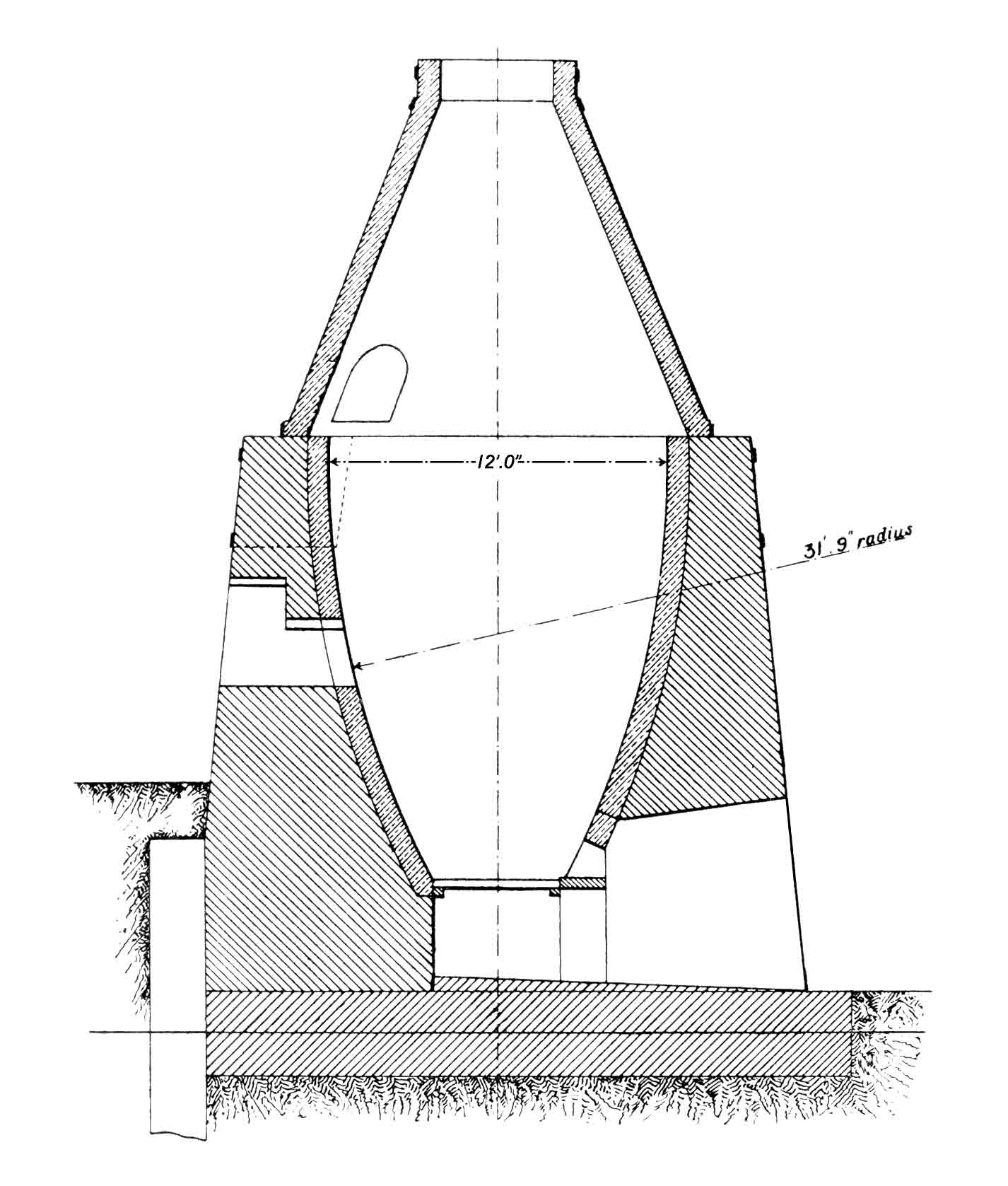
The construction of the bottle kiln was largely replicated in the later forms of batch-process static kiln. The base and the conical section were built from ordinary bricks and mortar (although concrete was occasionally used). Iron hoops around the outside of both the base and the cone provided tensile strength and allowing thinner brickwork. The lining of the kiln was made with “fire-brick” – the typical siliceous refractory of the early industrial period. The lining was made smooth and to a carefully controlled curvature by building against standard wooden formers. A doorway was made in the cone to allow the feed materials to be put in. Sometimes a second door was also provided half-way up the kiln. At the base (the "eye"), a grate of wrought iron bars was provided, and an access tunnel led from this to the outside. The air supply for the kiln passed through this tunnel, and it was common to align the tunnel towards the prevailing wind to improve the draught. A small access door between the tunnel and the kiln immediately above the grate was used to extract the finished clinker. All the side doors were bricked up during burning, and plants maintained a team of bricklayers for this and for repairs to the kilns’ refractory linings.
Slurry Backs
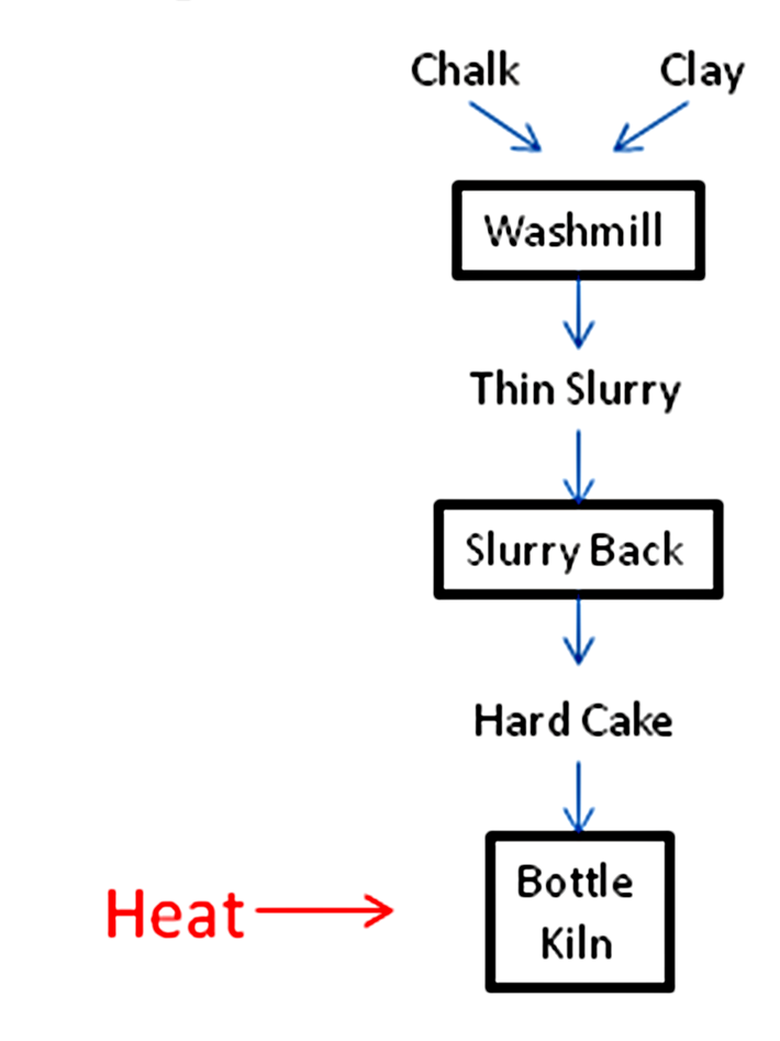
The feed for the earliest kilns was prepared by washing the ingredients together as a very thin slurry (a “slip” with ~80% water content by mass), and allowing it to settle in slurry backs. These were large tanks or reservoirs, often several hundred square metres in area, and 1-2 metres deep. This had the dual effect of allowing larger particles to drop to the bottom, and allowing water to be decanted from the top. Often the base of the back was made porous, allowing water to drain out. Early practice involved settling for as long as six months, after which a stiff cake (containing 10-15% water) was formed which could be cut into blocks for loading the kiln. The gritty material at the bottom of the mass was re-cycled or discarded. The process is identical in every respect with that used in the ceramics industry for centuries to produce fine-grained pottery clay, and was first used by James Frost at Swanscombe to prepare his “British cement” in 1825. Frost probably got the idea from Vicat. The obvious problem with this method was that, as production increased, inordinate areas had to be set aside for settlement.
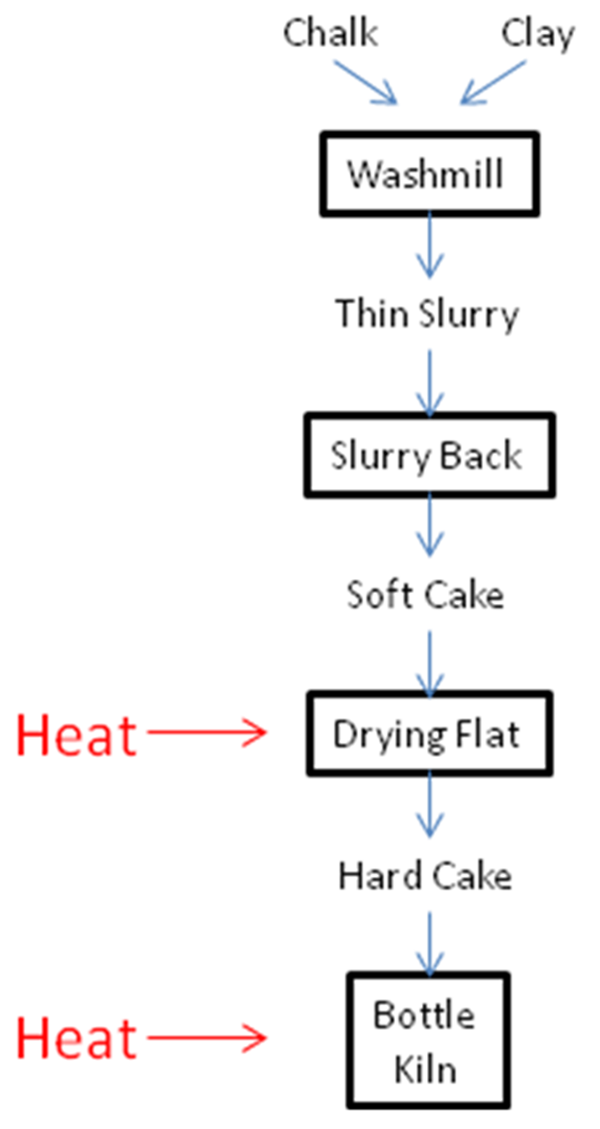
Drying Flats
The first attempt to get around this was to use separately-fired drying floors or flats on which the final drying of the 25% moisture-content cake was sped up, at some considerable extra energy expenditure, and this became the normal “wet-process” for bottle kilns from around 1850. Although some plants used waste heat from coking ovens, most plants bought their coke, and the floors (or flats) consisted of iron or brick surfaces on which the semi-dry slurry was distributed by hand, heated from below by a coal-fired furnace. Thus overall fuel consumption was increased in order to speed up the process and increase the productivity of a given area of plant land. The fuel used, on chalk materials, was typically 1.5 MJ/kg clinker. Where coke oven heat was used, the effective fuel usage could be twice this, because the fuel volatiles were almost invariably run to waste (i.e. to atmosphere).
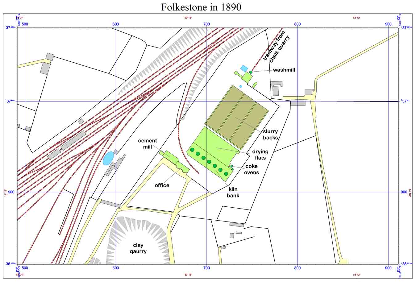
This standard format was usually organised in a linear arrangement, so that the distance for transfer of materials was minimised. The example shows the Folkestone plant, which did not progress beyond its initial design.
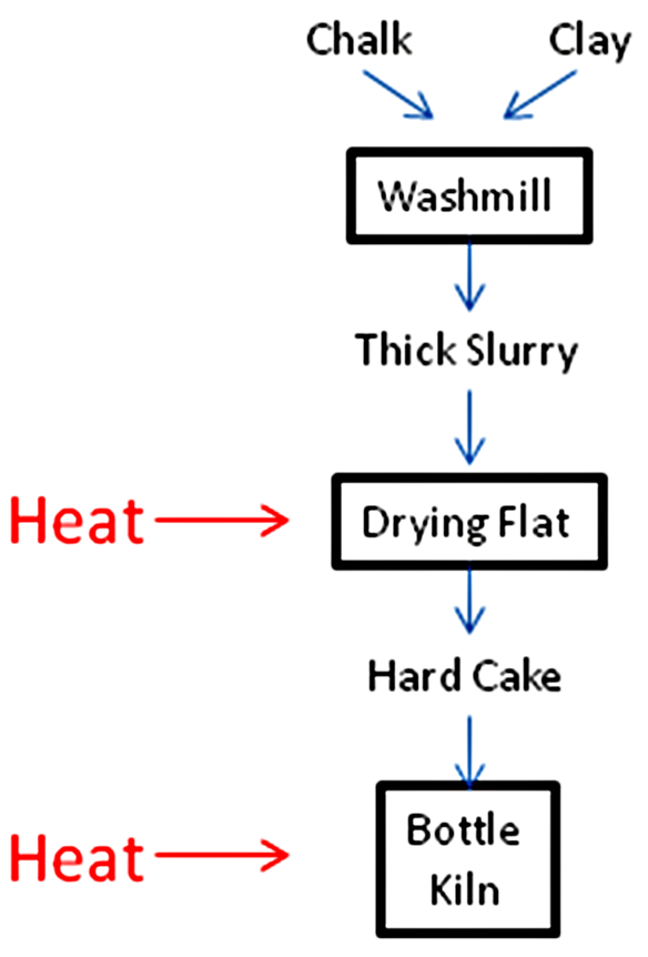
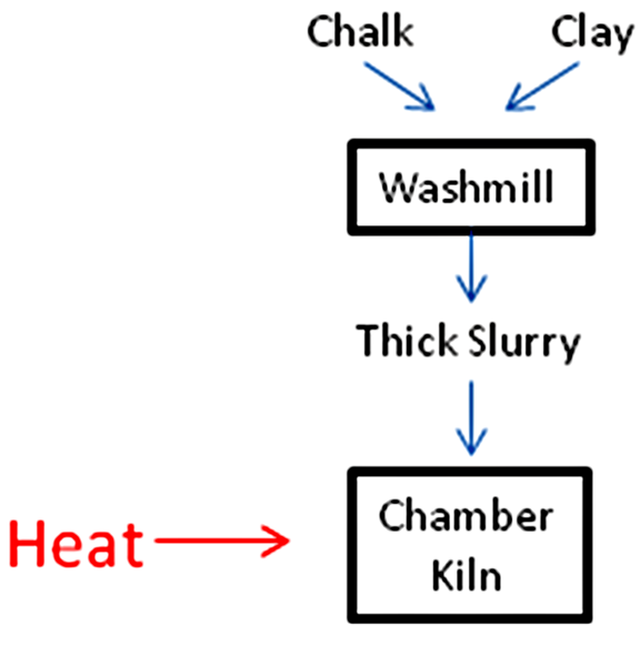
Thick slurry process
The next significant development (1870) was the thick slurry process of Goreham at Swanscombe. Here the slurry was washed at only ~40% water content. This precluded removal of the coarse material by settlement, so the slurry was re-ground with millstones to obtain the required fineness, incurring extra power consumption (although it was generally agreed that the resulting slurry was still considerably coarser than that obtained by settlement). The slurry was then immediately dried on drying floors, again with a further increase in pre-kiln fuel usage, but allowed the raw material processing time to be reduced to a few days. The fuel usage for drying of chalk materials was doubled compared to the "thin slurry" process, to typically 3.1 MJ/kg clinker. The replacement of bottle kilns with chamber kilns (see below) proceeded rapidly from the 1880s, but the installation of new bottle kilns continued in the less sophisticated production areas (such as Somerset) up to 1920. The last bottle kiln to operate was probably at Spinx, shut down in 1942.
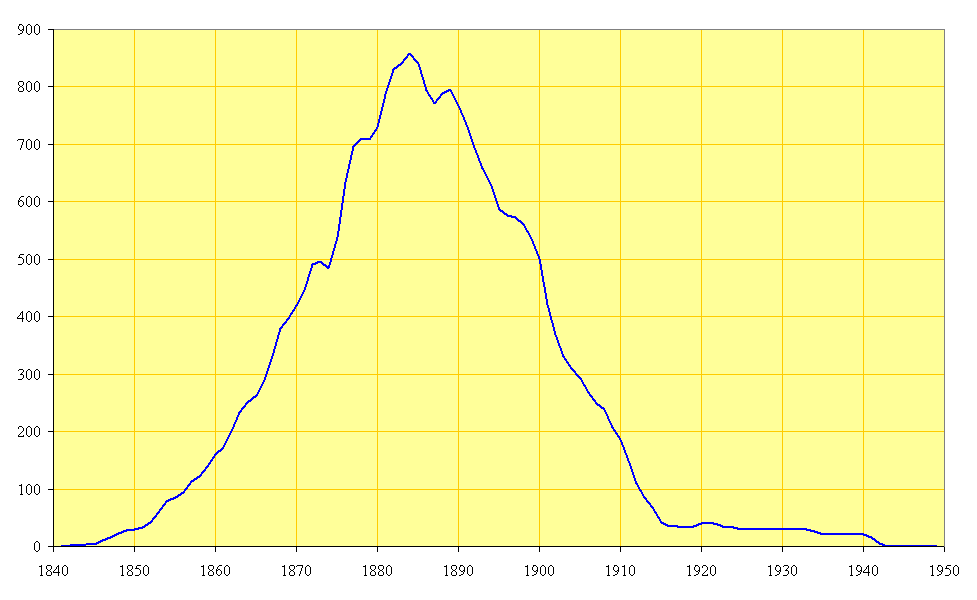
Number of Bottle Kilns in commission
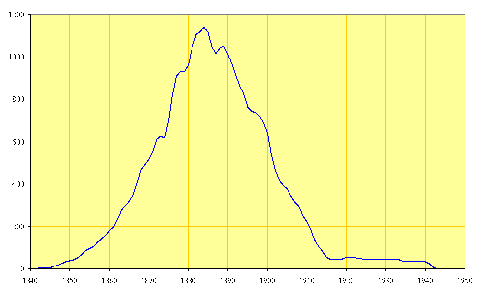
Capacity of Bottle Kilns in commission in thousand tonnes/year
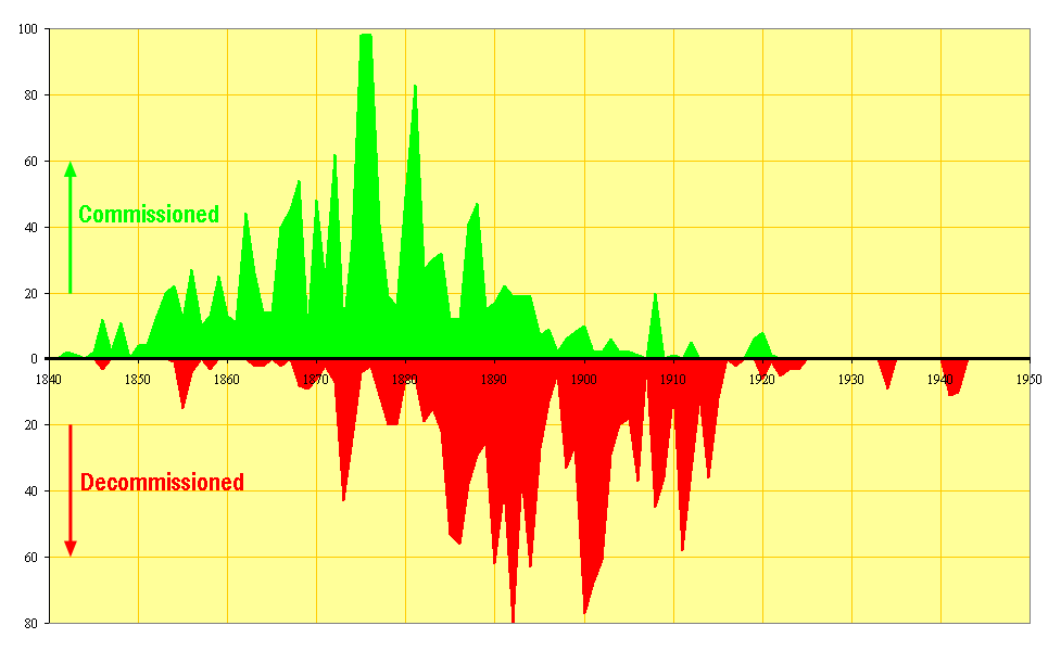
Number of Bottle Kilns commissioned and decommissioned
Chamber kilns
This led rapidly (1872) to Johnson’s development of the Chamber Kiln, in which the drying floor was connected directly to the kiln, the exhaust gases (of which there were more than sufficient) supplying all the necessary heat for evaporation.
Johnson can be credited with establishing this as a successful technology, although others, e.g. R. A. Gibbons at Robins (1867) and R. O. White at Swanscombe (1870) had patented and operated earlier variants.
The first kilns of this design were developed by adaptation of small bottle kilns at Gateshead during the period 1869-1872.
Traditional kilns used around 14 MJ/kg of energy of which 75% went to waste in the exhaust gas as low-grade heat, much diluted with air. Slurry of 40% moisture content, on the other hand, theoretically needs only around 3 MJ/kg of energy for drying. The chamber kiln allowed the construction of very compact cement plants with a low capital cost, and chamber kiln plants, typically with seven kilns, and making around 10,000 t/y, became the standard format for new ventures. By 1889, chamber kiln capacity exceeded bottle kiln capacity.
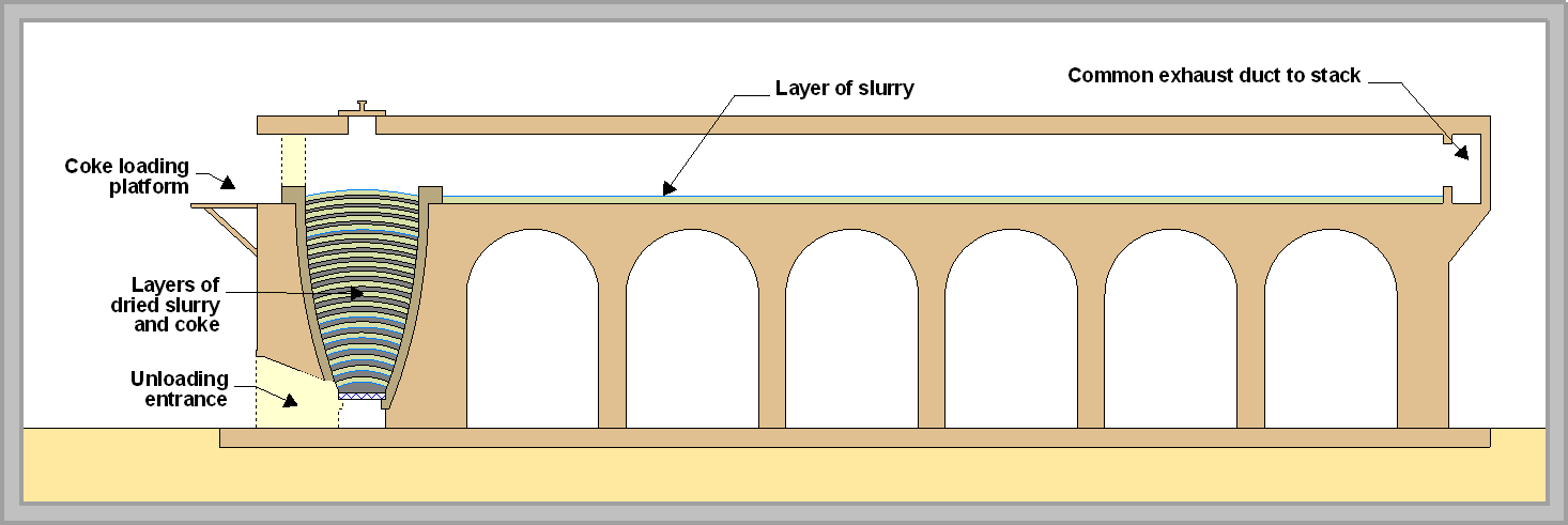
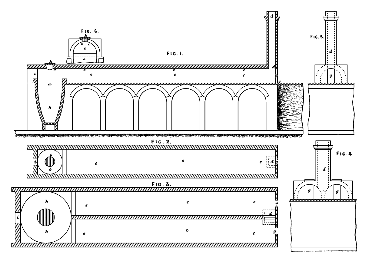
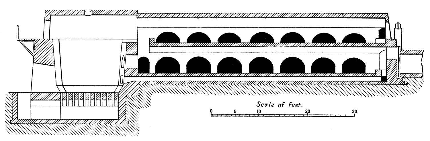
The design shown is as constructed on flat ground. On sloping ground, as was to be found at many plants, the chamber could be built into a hillside, hence saving on the amount of masonry to be erected. Johnson’s prototype kilns as described and depicted in his patent were of only ten feet in diameter, making 10 tonnes each, but the kilns were soon scaled up to the full 18 ft, making 30 tonnes. The drying chamber, of the same width as the diameter of the kiln had a specified length of 80 to 100 ft, later extended to as much as 120 ft. The floor tilted slightly towards the kiln end, allowing a thicker layer of slurry where the gas temperature was at its highest. Typically the slurry was about 350 mm deep at the hot end, and 100 mm deep at the cold end. The layer shrank in thickness by 50-60% during drying. The chamber could be charged by pumping. The gang of labourers filling the kiln consisted of strippers, who cut the dried material from the chamber floor and wheeled it to the kiln, fillers, who distributed the lumps carefully in the kiln, and coke boys, who carried skips of coke up to the kiln top. All this was done under the supervision of the kiln burner, who would also spend time watching the progress of the other kilns in the block. The drying chamber had a reasonably high arched masonry roof which allowed plenty of room for the strippers to work. The roof was 450 mm thick and was usually open to the elements.
George Burge Jr (Johnson's collaborator at Crown) also patented a somewhat similar chamber kiln design in 1872, claiming it could be used continuously, although this probably did not in practice extend beyond “topping up”. Subsequent developments of the chamber kiln design involved increasing heat exchange with increased surface areas and thinner layers of slurry, and it was found that as much as twice the kiln’s raw material consumption could be dried, although the Johnson kiln remained popular to the end because of its simplicity.
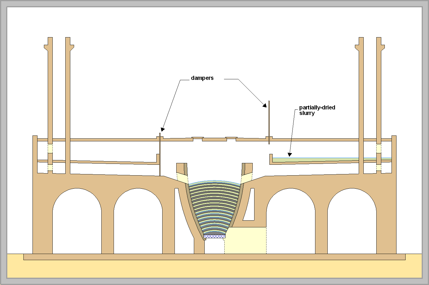
Already mentioned is the Gibbons kiln (1867), which had a pair of drying chambers used alternately. Thus one chamber could be heated while the other was being replenished with slurry or stripped - a marginal time saving since, with the advent of efficient slurry pumps, a conventional Johnson chamber could be charged with slurry in an hour or so. However, the Gibbons patent claimed that the kiln could be operated continuously. Except for "topping up" this certainly was not the case. The four kilns erected by Gibbons at Robins seem to have been the only ones of this type. Similar in design and concept, but with double kilns connected to the pair of chambers was the Killick kiln.
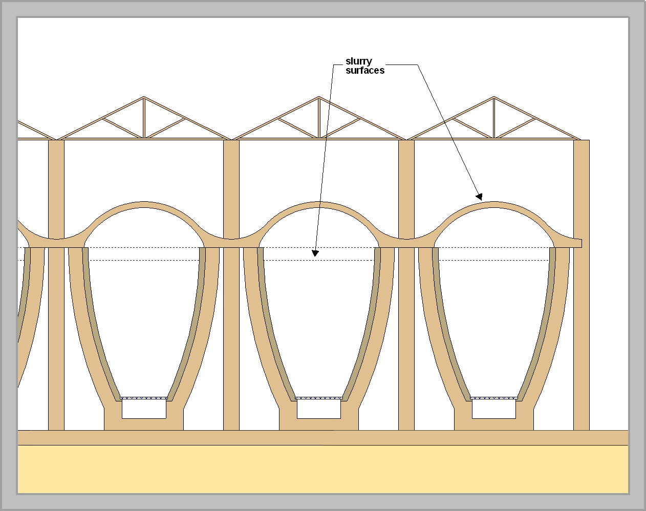
The Michele kiln used the design of the Johnson kiln, but with a lower chamber roof. Slurry was placed in the chamber and also on top of the arched roof of the chamber, with a further light roof over the top to keep the rain out. Working was cramped inside the chamber, and the placing of slurry by hand on the arch was labour intensive, but the design allowed a much shorter chamber to be used.
The Batchelor and Hilton kilns were similar and consisted of two or three short flat chambers stacked vertically. These and the Michele kiln suffered from the flimsy design of the brick arches, necessarily thin to allow heat exchange, but prone to collapse during heating and cooling, and requiring complete shutdown for repairs. The sturdy Johnson design did not suffer from this defect. The need to minimise the height of multi-level chambers led to the construction of chambers with low roofs, making the working conditions of strippers even more unpleasant.
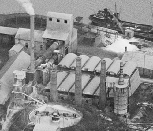 Six Batchelor kilns sheltered with corrugated iron roofs, just decommissioned at Vectis in 1926. To the right is a Schneider kiln for burning the excess slurry.
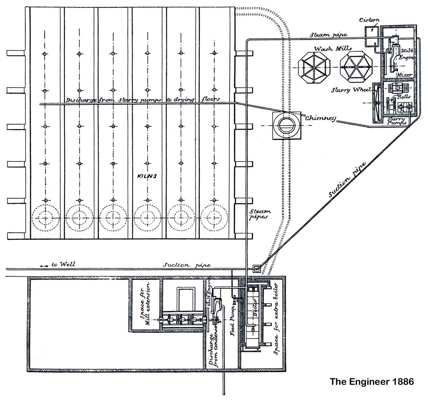
The “perfection” of chamber kiln technology led to a plateau in innovation in the British industry in the 1890s, allowing foreign, and particularly American, industries to overtake it with lightning speed, almost before anyone realised it. The apotheosis of chamber kiln technology can be seen in the 1886 description of the early Arlesey plant (“New Portland cement works at Arlesey”, The Engineer, 62, October 8, 1886, pp 291-292).
Read the entire Engineer article.
The plant's footprint was tiny. Equipment consisted of a boiler feeding two steam engines - one driving the washmills and associated equipment, and one driving the four flat-stone finish mills. Six kilns allowed one kiln to be turned around every day, Monday to Saturday. The design is "Just In Time", with no storage of materials at all, except for the room (bottom left) in which the finished cement was kept. Each working day, a kiln would be emptied of 20 t or so of clinker, and hand-broken clinker was fed to the finish mills. The dried slurry was stripped from the drying chamber, loaded into the kiln, and the kiln was re-lit. The washmills were started up as soon as the drying chamber was clear, fed from tram cars delivered direct from the quarry. Some attention was paid to measuring the amounts of raw components fed to the mill, although, in view of raw material variability, this gave little guarantee as to the chemistry of the product. The finished slurry was pumped directly to the drying chamber without any attempt at blending.
All these operations were accomplished in daylight. Because little intervention in the operation of the kilns was possible once they had been lit, the plant was left unattended at night and on Sundays. The cement contained free lime, varying from high to extremely high, on account of the coarseness of the slurry, the variability of the slurry composition and the variability of burning. Cement was therefore always stored for several weeks to allow unsoundness to "die down", and the capacitance of the cement store was the end-user's only protection from the extreme variability of the finished product. Given cheap fuel (amounting to around 0.6 t per ton of cement including motive power), the process was extremely cheap to operate. The standardisation of the industry along these lines ensured that end users had little recourse but to "take what they were given". During the following ten years (1886-1895) the British industry was quietly and irreversibly overtaken by the foreign competition.
“Off-the-peg” cement plants equipped with chamber kilns were still being started in the third decade of the 20th century. A good description of a large, well-run and relatively profitable chamber kiln plant is given in The Engineer in 1902 (read this).
Double Burning
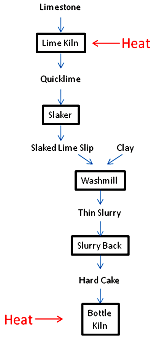
The above developments were predicated by the particular materials handling techniques of chalk/clay mixtures. These materials can not be ground when damp, but also, because of their micro-porous nature, they can not be easily dried in lump form, so that wet grinding and handling was more or less mandatory. Where hard limestone was used, early practice was to “double burn”, making lime from the limestone, slaking it to a thin slurry, then combining it with clay and proceeding as with the wet process bottle kiln. Joseph Aspdin, burning hard limestone at Leeds and Wakefield, used and patented this process. It was also used at Harbury, the first plant to make true Portland cement from Lias materials. There, it was used for about 25 years before a normal, dry process rawmix was adopted. Thermodynamic modelling of this process for typical Harbury raw materials showed that, for a stone requiring 14.5 MJ/kg to burn directly to Portland clinker in a bottle kiln, in double-burning the first (lower temperature) stage would require 10.3 MJ/kg, and the sintering burn would require a further 12.7 MJ/kg. It obviously involved a virtual doubling of the time, manpower and energy cost of pyroprocessing, but it shows the lengths to which manufacturers would go in order to avoid grinding hard materials with the primitive equipment then available.
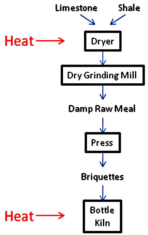
Dry Grinding and Briquetting
Developments in grinding technology in the late nineteenth century allowed limestone and shale to be ground to a powder, and with a small water addition (5-10%) this raw meal could be pressed into briquettes that could be burned in a bottle kiln, this being the “dry process” bottle kiln method. The technique was most successfully used on Chalk Marl and Blue Lias materials, where inhomogeneity of the mix was less of a problem. The employment of continuous shaft kilns followed naturally from this.
Continuous Shaft Kilns
Here briquettes of rawmix and fuel are continuously added at the top of a shaft and gradually descend under their own weight. A “burning zone” is maintained in the middle of the shaft, where the fuel burns out, and below that, the combustion air passes up through the mass of clinker, cooling it. The clinker is withdrawn from the bottom, the rate of withdrawal being such as to maintain the burning zone in the correct position. The main technical problem with such kilns was the tendency of the sintering clinker to form a solid plug preventing downward flow, or to form thick coatings on the brickwork which would eventually choke the kiln. The designs that emerged were aimed at tackling these problems. There were many designs for shaft kilns, but the only ones used to any extent in Britain were the Dietzsch and Schneider kilns.
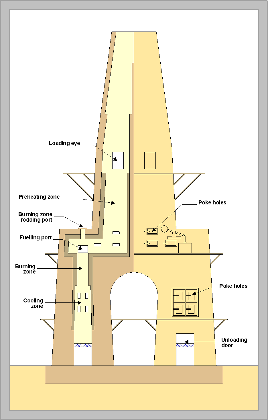
The Dietzsch kiln (1885) typifies the problems that had to be overcome. The design is all directed towards enabling the use of brute force to persuade sticky material to gravitate through the kiln. It had a pair of lower shafts of 3-8 ft diameter, connected to a pair of upper shafts of 15-25 ft diameter, surmounted by a short common stack. The upper shaft was fed at the top with lump or briquetted raw material only. Dried and pre-heated material withdrawn by hand from the base of the upper shaft (the "hearth") was dragged into the top of the lower shaft, with added layers of coke or coal. The lower shaft was provided with numerous poke-holes around the hearth and above the top of the burning zone. The constriction of the kiln in the top of the lower shaft maximized the draught at that point. An expansion of the cross-sectional area from the burning zone downwards discouraged sticky clinker from impacting on the walls. Because fuel was added at a point where the feed was already above red heat, it would catch fire immediately, and this allowed ordinary bituminous coal to be used: this was a major reason for the adoption of this kiln during times of coke shortage. The two-kiln assemblage would produce 100-150 tonnes/week depending on size and efficiency of operation. However, because three separate labour gangs were required to feed the kiln, to transfer the preheated material and to discharge the clinker, all these needing painstaking round-the-clock attention, the process was relatively labour-intensive, and this limited its popularity. All the operations involved strenuous work, often at height, and clearly, in the operating conditions around the hearth, it was difficult to get a constant ratio of fuel to feed, the dosing of material to the burning shaft involving measuring feed and fuel "by eye". For this reason, the kilns produced a large amount of over- and under-burned product, and it was common to keep an ordinary bottle kiln nearby for re-burning the latter. Despite these difficulties, the low fuel consumption of these kilns was immediately clear. Heat consumptions in the range 5-7 MJ/kg were reported, and could clearly be pushed lower (although this excludes any heat used to dry the raw material). Thus wherever raw materials were dry and fuel was expensive, as on the Continent, new designs of shaft kiln were rapidly developed. On the other hand the wet materials and cheap fuel in the English industry discouraged any new developments at home.
The developments of the Dietzsch kiln consisted mainly of eliminating the intermediate handling stage. Straight shaft kilns included the Aalborg, Schoefer, Riisager, Hauenschild, Hotop, Stein and Perpignani-Candlot kilns. These are well described in texts such as Redgrave. Although common on the continent, few of these were used in Britain.
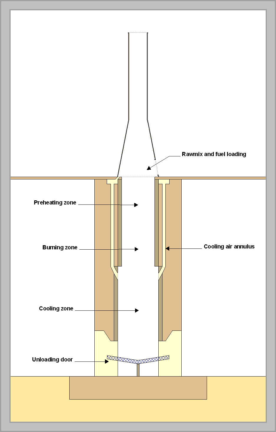
The Schneider kiln (1898) was marketed by F. L. Smidth, and was much simpler, with a single shaft, typically 8-10 feet maximum diameter and 40-50 ft high, surmounted by a stack for natural draught. Blockages were discouraged by having a constriction in the diameter above the burning zone, taking the pressure off the hot material; by keeping the burning zone lining cool, and by keeping fuel away from the lining. Because fuel and rawmix were fed together, only coke could be used.
The burning zone lining was cooled by diverting air from the cooling zone into an annular space behind the burning zone refractory. By means of dampers, the cooling air could be diverted to any sector where build-up might be occurring. The cooling air discharged through an annular collecting duct, into the stack. Fuel was kept away from the lining by packing rawmix briquettes around the periphery before adding each fuel layer. The effect of these strategies was, of course, to deliberately produce a zone of under-burnt material around the edge of the charge, so that a proportion - say 5-10% - of under-burnt product was considered good operating practice. This meant that clinker still had to be manually "picked over" before grinding.
In its simplest form, the kiln would make 70-100 tonnes/week. The Schneider kiln, unlike the others, had a continuing career, with various improvements:
- Forced draught, usually obtained by pressurizing the air entering at the base, which increased output to 120-200 tonnes/week
- Automatic discharge into a conveyor, using a rotating toothed grate at the base of the shaft
- Automatic feeding by conveyor
- Incorporation of the fuel in the rawmix briquette – the “black meal process” – which gave a more uniform burn and controlled burning temperature.
Autonomous Schneider plants continued in use at Burwell, Cousland, Halling Manor, Isis, Lee’s, Linley and Saxon into the 1920s. Many more installations found intermittent use for burning surplus slurry from chamber kilns. Black meal plants were installed at Plymstock and South Ferriby as late as the 1950s. Such plants continue to be installed – often with sophisticated modern control systems – in developing countries in localities where the market is small.
The shaft kiln became the first genuinely energy-efficient process: a sufficiently long shaft could recuperate most of the heat in the clinker and in the exhaust gases, and heat consumptions of ~5 MJ/kg were being reported before 1900. However, this was only a serious technical proposition in the hard-rock areas, which at that time in the UK constituted a tiny proportion of the production capacity. Shaft kilns began to be used in the chalk areas in two contexts: surplus dried slurry from the more complex chamber kilns was burned in adjacent shaft kilns, or thick slurry was dried to a pressable consistency on drying floors and burned in shaft kilns. In either case, the energy penalty of the inefficient drying processes had to be carried, and this probably explains the slight enthusiasm for shaft kilns in the south-east. In America, on the other hand, chamber kilns were almost unknown (and where they existed were introduced by British entrepreneurs). The birthplace of the American industry was a hard-rock area, and a dry process was a reasonable choice. The high cost of labour favoured a continuous process, so continuous shaft kilns were the rule before the advent of the rotary kiln. On the continent, the cost of fuel stimulated the use of more efficient shaft kiln processes, so shaft kilns remained numerous there into the middle of the twentieth century. Thus by 1900, energy efficiency in the UK was almost uniquely poor.
A key factor in technical change was the availability of coke. Most static kilns had to use hard coke: coal could not be used because it caused collapse of the charge, and because, during the slow heat-up of the charge, the coal would lose its volatiles – and half its calorific value – before ignition took place. During the period of rapid growth of the coal gas industry, particularly around London, coke was produced in great quantity, almost as a waste product. However, towards the end of the nineteenth century, gas works increasingly used the producer/water-gas process to supplement their production and decreased the availability of coke. This trend was later exacerbated by the change-over of municipal lighting from gas to electricity. This, and certainly not the price of energy (which was still as low as anywhere in the world), was a major factor in the change-over to rotary kiln production.
Hoffman kilns
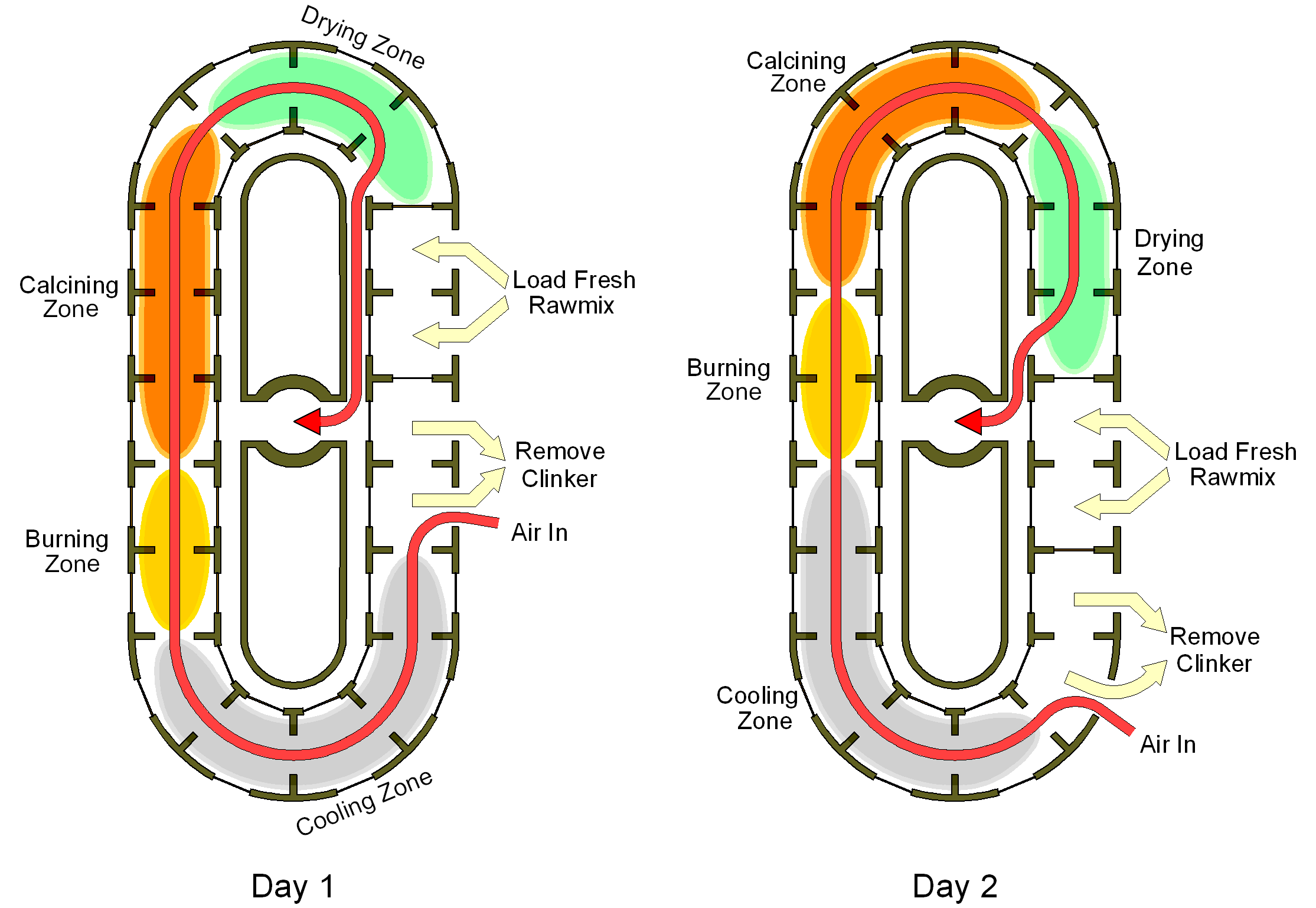
These appeared around 1875, and were an evolutionary dead-end, but must be described because they were used, always with little success, at a number of locations. The Hoffman kiln was designed for making bricks, and continued in that capacity until the late 20th century. It consists of a circular arrangement of chambers, each functioning as a static kiln. Each has closable doors to the outside for charging and emptying, to a common exhaust flue on the inside of the ring, and to each neighbouring chamber. The assembly is rendered pseudo-continuous by driving the “burning zone” around the ring. An emptied chamber is neatly stacked with briquettes and fuel, with spaces left for the charge to breathe. Once filled, exhaust gas from the previously-filled neighbouring chamber is ducted through it. As the cycle of emptying and loading proceeds around the ring, the burning zone approaches and the chamber gets hotter until its charge fires. Cooling by combustion air then takes place until the cycle has passed right round the ring and the chamber is emptied. The operator can adjust the temperature and location of the burning zone by judicious use of dampers and small additions of fuel through ports in the kiln roof.
Fuel consumption of around 7 MJ/kg was typical, and could potentially be lower, but raw material had to be dried and briquetted beforehand. Because of the clamp arrangement of stacked briquettes, the uniformity of burning was always poor and a large proportion of under-burned material was always produced. These kilns are described in great detail in most of the contemporary texts, often, one suspects, because the process was rather intriguing, and it was felt that it "ought to work". This probably explains why so many were installed, despite repeated demonstrations of their impractical nature.