The escalation of the size of rotary kilns occurred in parallel with the emerging pre-eminence in Britain of the Wet Process of manufacture.
In 1900 the standard length of kilns was 60 ft, and many were sceptical as to the value of longer kilns. However, by 1901 Thomas Edison, to general derision, was already planning to install 150 ft long kilns with a 19:1 LD ratio and these when they got underway in 1905 demonstrated the much greater ease of use and economy of such a system. After overcoming the engineering challenges of such large plant, the trend towards longer kilns was rapid, and this resulted in well-behaved wet kilns. At this point the superiority of rotary kilns became clear and plants abandoned the static kilns that they had previously kept in reserve as “insurance”. Successively longer wet kilns were installed from then until the demise of wet process.
The installation of the first 70 m kiln (at Wouldham) led the Chief Alkali Inspector to comment in his Report for 1911: “The ultimate limits of practical effort are still in the future, but from the great progress already made as regards the dimensions of the rotary kiln, it would appear that the maximum size of this particular type must now be closely approached”. Kiln lengths, in fact, ultimately reached over 230 m.
The development in the late 1920s of internal kiln heat exchangers (mainly in the form of chains) considerably improved the efficiency of the wet process, and dry process kilns almost disappeared by 1930. The failure of the early dry processes, in addition to the relatively small energy-consumption benefit, was probably due to the poor methods of blending of the early days. The dry process was from the outset common (and remained so) in the United States, but the raw materials used there were commonly argillaceous limestones, with which poor blending would have had relatively little deleterious effect. With the installation of larger wet process kilns, the advantages of finely-ground rawmix and painstaking blending became apparent. Very large slurry storage systems, allowing very steady kiln feed chemistry, became standard. The use of chain heat exchangers which began around 1930 (having been pioneered by F. L. Smidth) had a revolutionary effect. Most kilns up to that time used only the convective suction produced by a tall stack to draw gases through the kiln, and dense chain systems caused a greatly increased restriction to gas flow, necessitating the fitting of induced-draught (ID) fans before the stack. However, by greatly increasing the area available for heat exchange, kiln outputs were increased by (typically) 40%, and fuel consumption was, if anything, somewhat reduced. It became apparent that scaling up kilns would yield economies of scale, and large plants (notably Bevans and Swanscombe) replaced large numbers of small kilns with fewer large kilns. The longest kilns in use were as follows:
The general trend was towards longer and wider kilns. A distinct upper limit of diameter was reached at Northfleet where refractory life was reduced by a lack of rigidity of the shell resulting in "ovality". Kilns longer than the 650 ft at Northfleet were installed in a few places abroad, the longest (to my knowledge) being the 232 m FLS kiln at Clarksville Missouri, which operated 1967-2009.
The Nature of Slurry
It is the use of feed in liquid form that distinguishes wet process kilns from the others, and the peculiar characteristics of the slurry affected the way in which the technology of wet process kilns developed.
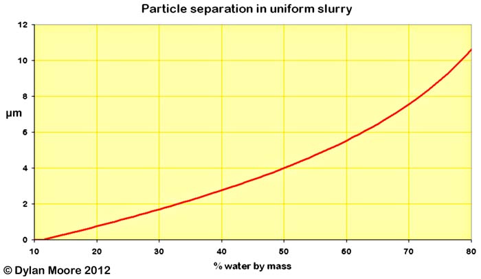
Wet process slurry consists of fine particles (mostly below 75 μm) of calcium carbonate and clay minerals suspended in water. The density of calcium carbonate is 2710 kg/m3, and that of the clay minerals is slightly less - 2650 to 2700, giving an average of around 2700. So a slurry containing 40% water by mass (this being the normal way of measuring it) at 20°C contains 64.33% water by volume. As a simple approximation, if the solid particles are 10 μm spheres in a close-packed arrangement, then the distance between particle surfaces varies thus:
It is this thin layer of water that allows the slurry to flow. As the separation of particles increases with increasing water content, so the tendency of the particles to "lock together" is reduced. This "locking" of particles in random contact manifests itself as "yield stress", and slurries behave as Bingham plastics. Modern slurries required a fairly tight control of water content. It had to be kept high enough to produce a slurry that could be pumped from place to place, to allow it to be stirred for blending purposes, and to flow easily into a hot, dusty kiln. On the other hand, excessive water content was to be avoided because of the cost of evaporation and in order to avoid "settling out" (with change of chemical composition) during storage.
The cost of evaporating the water in the kiln is the reason why the wet process is now extinct. To evaporate 1 kg of water requires 2442.6 kJ of latent heat at 25°C. But in addition, the temperature must be raised to 100°C at least, requiring another 182.6 kJ of sensible heat. If the heat is supplied by burning typical coal in air, then the combustion gases must also reach 100°C at least, requiring a further 86.9 kJ of sensible heat, giving a total of 2.7121 MJ. From this it is possible to calculate the minimum energy penalty for water evaporation: for a kiln using 1.56 kg of dry rawmix to make 1 kg clinker, 20% water in the feed requires 1.06 MJ, 30% requires 1.81, 40% requires 2.82 and 50% requires 4.32.
The original slurries produced by the pioneers of the cement industry contained very large proportions of water - 75% or more by mass - most of which was decanted before further processing. The Goreham "thick slurry" process resulted in comparatively thick slurries - less than 50% water - in which, in the interests of rawmix homogeneity, any tendency to settle out was discouraged. The maturing of this technology led, by the end of the nineteenth century, to slurries of the consistency that remained typical throughout the twentieth century. This was sufficiently thin to pump down pipelines of up to a kilometre in length, but thick enough to remain stable without settlement. The amount of water needed to produce a slurry of this viscosity varies according to the nature of the raw material. Two factors tended to increase the amount of water needed:
mineral particles that have highly hydrophilic surfaces
a large proportion of ultra-fine particles in the rawmix
Clays in general are both hydrophilic and fine, and clays milled alone produce pumpable slurries with 60-70% water content, although some comparatively rare "swelling" clays require much more water: a bentonite clay paste with 95% water is practically solid.
Calcium carbonate particles are not particularly hydrophilic, but the fineness of the particles produced on grinding varies from coarse in the case of hard limestones to ultra-fine in the case of soft chalks.
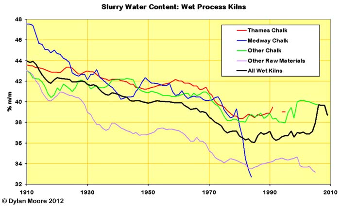
Plants in the heartland areas of the early industry almost all used fine clays and soft chalks. Typical slurry in the Thames/Medway area contained 40-45% water. Lower Chalk and Chalk Marl is distinctly harder than the Upper Chalk of the Thames, and could yield slurries around the 40% mark, but in many locations the argillaceous component of the marl contained montmorillonite with a high water demand, reversing this trend. The northern chalks of Humberside and Ulster are much harder and slurries of around 38% water could be obtained. When the industry spread into hard limestone areas, it became possible to make slurries with water content in the low 30s, although this was not always realised.
For centuries, ceramic slips had been "thinned" by the addition of a small amount (~0.1%) of sodium carbonate. From the 1930s onward, a few cement plants found that by adding "thinners" of this sort to the slurry, the slurry could be made pumpable at a lower moisture content. These additives are deflocculants, that reduce the charge fields surrounding particles with hydroxylated surfaces. The economics of use involved balancing the cost of the "thinner" against the gains resulting from improvement in kiln fuel consumption, and at most plants the gains were too marginal to be worth the trouble. Furthermore, if substantial reductions in slurry water were achieved, kilns had to be substantially re-engineered to cope with the changed heat exchange requirement. With a gradual rise in energy prices, the balance changed, and the use of moisture-reducing additives became more the rule than the exception. A wide variety of potential additives emerged, including the following, usually as their sodium salts:
carbonate
silicate
metaphosphate
polyphosphate
lignosulfonate
polymethacrylate
These in many cases resulted in reduction of slurry moisture from the 40s to the mid-30s. At Rhoose, slurry moisture was reduced below 24% for a while. Little was achieved with thinners in the Thames/Medway heartland because of the nature of the clays used - salty alluvium or sulfate-bearing London Clay, and the marls contained montmorillonite: all these render conventional thinners ineffective. From 1980 onwards, thinners became problematic, because most of them contain sodium, and high alkalis in cement were becoming an issue. Dose rates were reduced, resulting in a rise in slurry water content.
Below is a chart showing the historical trends in slurry water content, based on a rather patchy database. Slurry water data is hard to come by. Although the technical press contained many detailed articles on wet process plants, with the earlier ones insisting on the "perfection" of the process, they were peculiarly reticent about stating the actual amount of water used, perhaps out of embarrassment. The chart at least gives the lie to the idea that slurry typically contained 30-35% water. The trends are affected by the innovations mentioned above, but most obviously by the gradual relocation of the industry out of the chalk districts.
Features of Wet Kilns
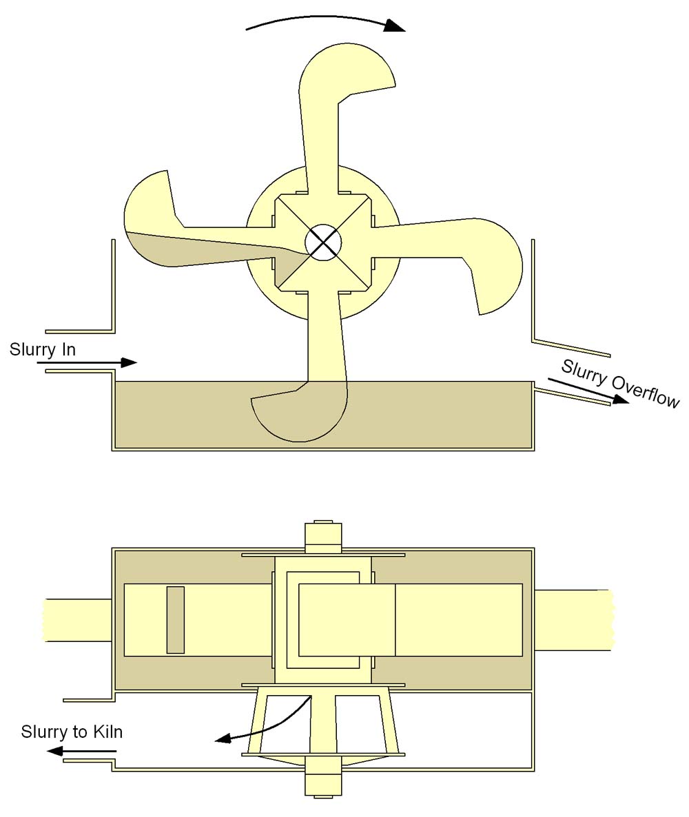
Because wet kilns were fed with slurry, unique arrangements were required to deal with this. For most of the history of wet kilns, slurry was fed to the kiln using spoon-feeders. These compared favourably with the primitive earlier designs - e.g. the Shoreham kilns.
Slurry is pumped from the kiln feed tank into the sump of the feeder. It overflows over an adjustable weir, so keeping the level in the sump constant. The spoons are rotated by a variable speed motor, picking up slurry and draining it into a trough that runs into the kiln feed pipe. The amount of slurry delivered is roughly proportional to the speed of rotation, as long as the pumping rate is sufficient, and as long as the speed is not so great as to slow down drainage by centrifugal effect - a problem that is greater if the slurry is thick.
In later years (1960s onwards), the tendency was to feed the slurry using a flow-meter and valve in a feedback control loop. Flow-meters were usually of the magnetic type: the slurry pipe passes between the poles of a strong magnet and a current is induced in the slightly conductive slurry, which is detected by a pair of electrodes. This avoids the need for moving parts in the very abrasive environment of the slurry. The control system would then make adjustments to an electrically or pneumatically actuated valve to control the flow-rate to a set-point value.
The high fuel requirement of wet process kilns means that the kiln must handle a large amount of combustion air - a mass-flow typically 2-3 times the clinker output - and handling this amount of gases places a limit on the output of wet kilns. On the other hand, there is plenty of combustion air for cooling of the clinker, and so even quite low-technology coolers could deliver cool clinker and usefully recuperate most of its heat. In efficient modern dry process kilns, the cooler design became much more critical.
Wet process heat exchangers
The early kilns were simple tubes into which the slurry was run. Slurry moisture content was typically 40-50% by mass. The temperature of the exhaust gases was typically in the range 500-1000°C, and the slurry would rapidly lose water in contact with this. As slurry dries, it first thickens, so that the interior surface of the kiln becomes coated with a layer of this, the layer becoming thicker as moisture is lost. When the moisture content drops below 30%, the slurry is (usually) no longer fluid, and takes on the consistency of a thick dough. Drying then relies upon percolation of the remaining water through the pore structure of this dough towards the hot surface. When the moisture content drops below 15%, the material takes on a porous, brittle, biscuit-like consistency. Thermal shock causes it to crack, and it breaks away from the coated surfaces in fragments varying in size from large slabs to dust.
Clearly, in a simple tube, the rate of evaporation depends upon the amount of internal surface area that can be coated with slurry, and the temperature difference between the slurry and the exhaust gas. In a kiln of limited size (and the early ones were rather short), this meant that high output could only be attained by maintaining a high exhaust gas temperature, and therefore wasting heat.
Two ways were identified to improve this situation by the early rotary kiln operators:
to lengthen the kiln, allowing more space for drying to take place
to line the kiln with “lifters” to agitate the slurry and pour it through the gas stream, and to add extra surface area.
Simple lifters consisted of lengths of iron “channel” attached to the internal surface of the kiln so that they would fill with slurry as the kiln rotated, and pour their contents across the gas stream as they rose to the top of the kiln.
In practice these were used only at the cold end of the kiln, since in the hotter zones they would invariably block solid and reduce the kiln diameter. Even at the cold end, they were not universally favoured, since the cascading of slurry caused a great increase in the amount of slurry spilling out of the inlet end of the kiln.
In the 1920s, beginning at Harbury, there was considerable experimentation with slurry sprays. Instead of pouring the slurry into the kiln down a wide-diameter pipe as was normal, the slurry was projected into the kiln through multiple small nozzles under pressure. This allowed the possibility that a large amount of evaporation could take place from the surface of air-borne droplets – a dramatically more efficient process, prefiguring the modern process of "spray-drying". However, it had several major disadvantages:
with the technology of the time it was difficult to measure or control the flow-rate of slurry into the kiln, good control of this being essential for stable kiln operation.
the unblocking and replacement of the nozzles was a 24-hours-a-day job.
fine dry material formed in suspension in the kiln gases caused a dramatic increase in the dust lost in the exhaust.
The feed-rate problem arose because only pressure could be measured with any accuracy, and for a given pressure, the flow-rate was affected by the viscosity of the slurry and by the size of the nozzles, both of which were variable.
Clearly, to get a fine spray, a small nozzle was required, and occasional over-sized particles in the slurry, or material baked onto the walls of the pipe in the high temperature conditions of the kiln, would regularly cause blockages. The very abrasive slurry, passing through the nozzles at high velocity, rapidly eroded them.
The third problem was in most cases decisive, in an era when there was essentially no capture of kiln dust. Such kilns would commonly emit a quarter of their total feed through the stack and deposit it over the surroundings.
Picture: Peter Ellis. In the space above the drier chamber, a spare atomizer assembly. Slurry is fed into the conical section, and the wheel at the base expels it centrifugally. Above are the gearbox and the motor.
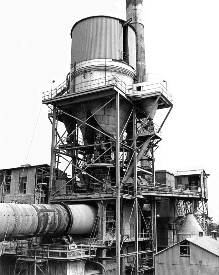
Picture: Peter Ellis. This shows the Humber spray drier, viewed from the southwest. At the centre is the hot gas duct rising from the kiln hearth, at the outlet of which the spray wheel is located. Particles fan out from this into the 9 m diameter drier chamber, and either drop directly down the "legs" of the chamber or are caught by the cyclones attached to the sides. The elevator and conveyor to the right returned the dust from all three kilns to Kiln A3 feed chute.
The spray concept had a brief swan-song in the 1970s with the addition of a modern spray-drier to Humber kiln 3. The concept was to extend the capacity of the kiln by drying the slurry in a preheater, while also improving the efficiency of the drying process. Hot kiln exhaust gas was ducted into a chamber in the centre of which slurry was fed to a spray wheel. This wheel had peripheral tungsten carbide spray nozzles and rotated at 3000-7300 rpm. The atomisation effect is produced by the rapid rotation of the wheel, so that the nozzle internal diameter could be 5 mm, avoiding (usually) any chance of blockage. The drier produced particles around 0.1-0.2 mm in diameter, so that cyclones on the exhaust ducts could easily capture most of the gas-borne solids. Because the kiln operated "dry", it was a simple matter to return precipitator dust to the kiln along with the dried slurry, and in fact all three kilns' dust was returned to kiln 3 in this way.
The effectiveness of the system was limited by the excessive care needed to ensure that the mechanically sensitive drier assembly should not over-heat. The exhaust temperature could not be allowed to go below 180°C for fear of wet conditions in the electrostatic precipitator, and could not go above 200°C without damage to the wheel. The system was therefore set up to inject water whenever temperatures rose, negating part of the efficiency gain. Furthermore, the amount of heat reaching the wheel varied depending upon the amount of hot dust carried out of the kiln to the drier chamber - a situation considerably exacerbated by return of precipitator dust. The effect of concentrating the raw material's sulfur and alkalis in one kiln had a devastating effect upon product quality control.
In the 1920s in Germany, external preheaters were developed, using kiln exhaust gas to dry out slurry, and drop more-or-less dry pellets of rawmix into the kiln, which was usually a simple tube without any further heat exchange devices. The most well-known of these were the Krupp "Konzentrator" and the MIAG "Kalzinator" or Calcinator. Only the Calcinator was used in Britain.
"Calcinator" of course is a confusing misnomer, since the device only raises the material temperature to around 110°C, with about 2-20% water still present, and no calcination takes place. The modern term "kalzinator" in German means precalciner.
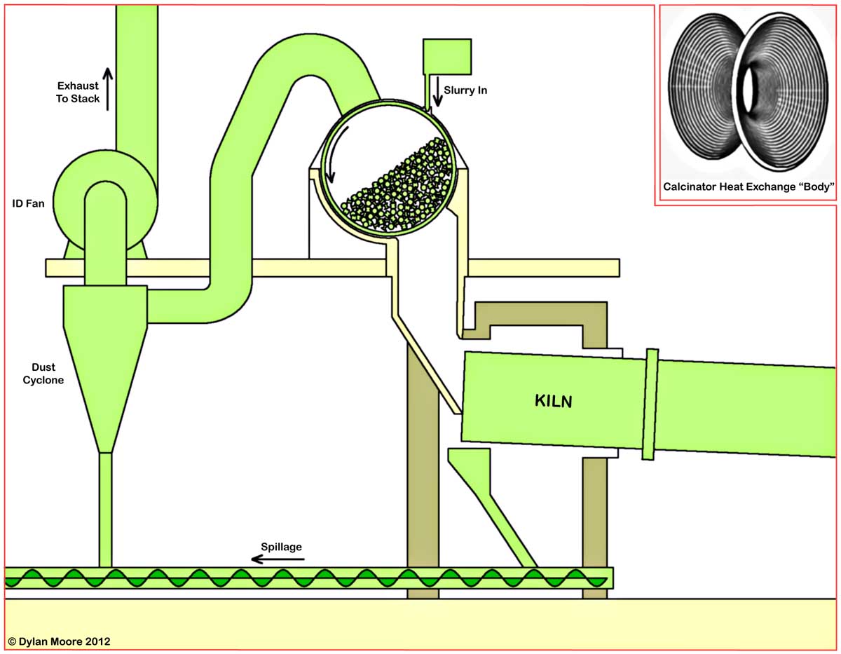
The Calcinator was patented in 1931 (GB 1933), and like the Krupp Konzentrator was designed for multiple processing applications wherever a preliminary drying stage was required. It consisted of a cast steel cylindrical cage mounted above the kiln inlet with its horizontal axis at right angles to that of the kiln.
The Calcinator cylinder had inside length slightly less than the kiln diameter, and internal diameter about 50% greater than the length. The cylinder was 45-50% filled with heat exchange "bodies" and rotated at about 1.5 rpm. Slurry was sprayed into the rising side of the cylinder, coating the heat exchange bodies, and the kiln gases passing through the charge supplied heat. In practice, most material spent only half a minute within the Calcinator: more or less clean bodies in the base of the charge were heated to about 300°C by fresh kiln gases, and on reaching the top chord of the charge dried the slurry, the plastic material spalling off on the falling side of the cylinder, and most of the material promptly dropping out at the "6 o'clock" position. Although in principle any heat resistant objects might be used as heat exchange bodies, in practice the MIAG-recommended form was always used, consisting of hyperboloid-shaped iron castings about 150 mm in diameter and 120 mm long, weighing about 3 kg (see inset in the above drawing). These met the requirements of supplying high surface area for heat exchange, an open packing structure allowing gases to pass through easily, and a shape that was self-cleaning, resisting any permanent build-up of dried slurry. The bodies wore down and had to be continually topped up, at a rate of about one for every 150 tonnes of clinker made. Material spilled at the kiln inlet and cyclone dust, both of which were plentiful, were usually returned at the kiln inlet. The partly dried material produced by the calcinator was intended to be fairly wet (around 12-15% water) in order to retain "nodule strength" and minimise dust generation in the kiln. In practice, a mixture of damp coarse material and dry dust was produced, and Calcinator operation required a compromise between two conditions: too-damp nodules caused build-up on the back-end chute and excessive spillage, while dusty over-dried material was blown back into the Calcinator and blinded it. The moisture content for the compromise condition was strongly affected by the rheological properties of the raw material. Some plants could only operate at around 15% moisture, but the most successful Calcinators, at Oxford, operated at 3-6%.
In the 1930s in Britain, the Calcinator was seen as an alternative to the installation of "long" kilns such as were being promoted by FLS, and could be retro-fitted on older, short kilns. The first UK installations were on kilns 1 and 2 at Oxford in 1933, and a number of installations followed throughout the 1930s, notably at four of the five Alpha plants, as follows, in date order:
The early indications were that Calcinators gave improvements in output and energy efficiency, but operators became more sceptical with time. It would appear that, with meticulous attention to detail, good performance could be maintained, but this involved labour expense. A dedicated operator was required around the clock to keep the equipment clean and flowing properly, and any attempt to economise on this front led to rapid deterioration of the system. Other considerable demerits were an inherently leaky construction, causing waste of fan power and unpredictable changes in kiln airflow, and a consistently high dust loss. Because of the tendency of the cage to build up and block with baked-on material, it was necessary to "tap" the cage (with a sledge-hammer!) at least once a shift, and the opening of doors during this operation caused massive inleaks and loss of kiln draught. On seven of the twelve installations, the calcinators were subsequently removed and the kiln fitted with chains and fed with slurry. Although sometimes (but not always) resulting in slightly higher energy consumption, these changes were at worst cost-neutral, because of the resulting simplification and steadying of the process.
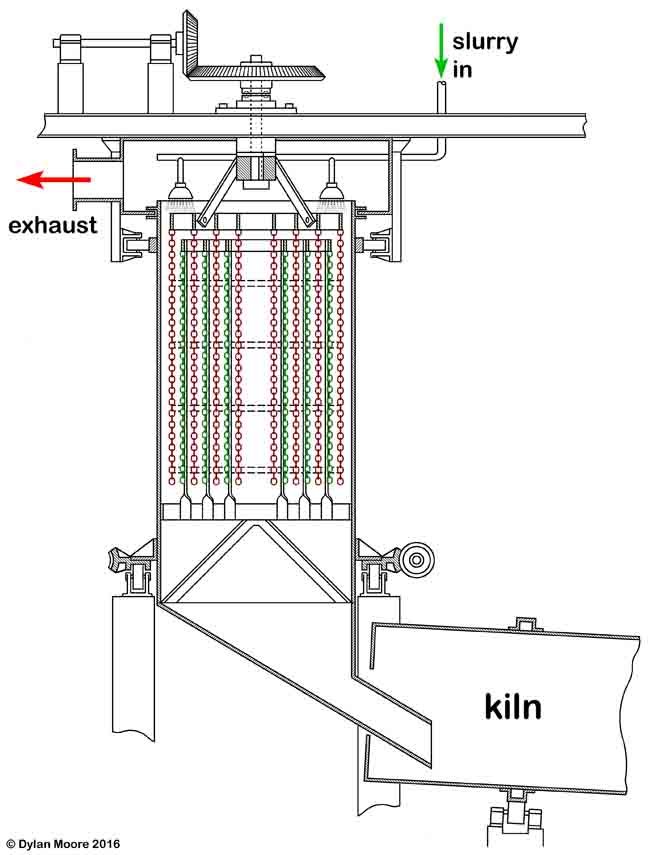
Layout of Polysius Slurry Dryer: "static" chains in green, moving chains in red.
While Krupp were developing their Konzentrator and MIAG their Kalzinator, Polysius were developing their own preheater, with a slightly different principle, patented in Germany in 1929. The design consisted of a vertical cylinder, containing seven concentric circular arrays of chains hung vertically, circles 2, 4 and 6 being static, and circles 1, 3, 5 and 7 being rotated about a vertical axis. Slurry was sprayed in at the top of the chain array. The jostling of the adjacent curtains of chain was intended to intercept the falling slurry and dislodge the dried-on material. As an option, the body of the dryer could also be counter-rotated. As with the calcinator, a residual moisture content of a few percent in the dried material was necessary to minimise formation of fine dust.
Only one was installed on a new installation in Britain - South Ferriby A1 in 1938, but a few more were retrofitted to existing wet process kilns around the same time, including Aberthaw kilns 1 and 2 and Sundon kiln 2, the latter being removed only a few years later.
Another strategy employed during the post-WWI period was to accept the inefficiency of the kiln, and put the hot exhaust gas through a "waste heat boiler" - a heat exchanger that produced steam that could be used to generate electric power. This was employed at a number of sites, but few did it for any length of time. There were several difficulties. Grid-supplied power was always likely to be cheaper. The large amount of dust in the exhaust gas could block the heat exchanger. More subtly, the power plant would tend to become a "tail wagging the dog", with the kiln controlled in a such a way as to keep the power plant running smoothly, rather than to make good clinker. Installations, all from the 1920s and 30s, included Cliffe, Rugby, Beddington, Swanscombe and Masons.
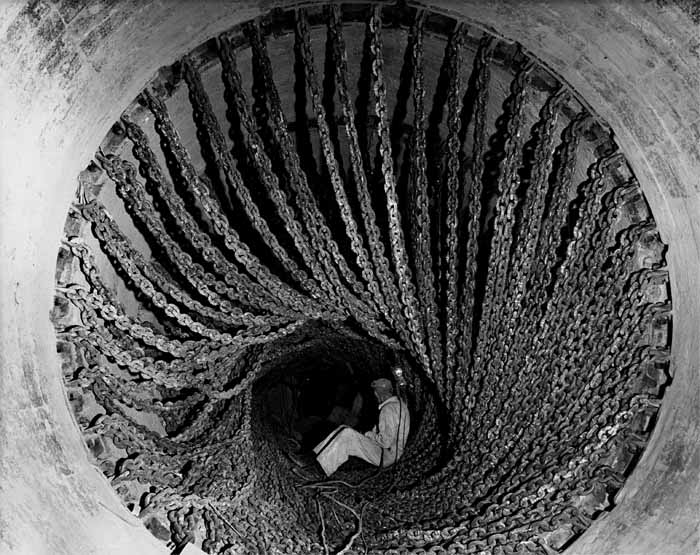
Although calcinators developed to a limited extent during the 1930s and some continued in operation for 40 years, from 1930 onwards, the dominant technology for maximising the thermal efficiency of wet process kilns took the form of chain heat exchangers. After initial installation on the FLS kilns at West Thurrock and Ketton, the technique was rapidly copied, and by 1935 the majority of wet kilns had chains. These remained, with little variation, the standard form of heat exchange in wet kilns until they became extinct. The idea is simple: heavy chains (typically with links 100-150 mm in diameter) are attached to the inside surface of the cold end of the kiln. They may be hung vertically from one end, or formed into loops or “garlands” by attachment at both ends. As the kiln rotates, the hot chain on the “floor” of the kiln is soaked and coated with slurry, and heats it up. Further rotation lifts the chain up into the gas stream, where hot gases re-heat the chain and dry adhering slurry. The available surface area contributed is huge, but the drying effect is achieved without violent agitation, thus minimising dust generation. Unlike fixed lifters, the chains are continually flexing, so they should not “block” or build up permanent coatings. Chain systems might occupy between 10 and 50% of the length of the kiln. Chain systems present a significant resistance to gas flow and needed a powerful fan to draw the exhaust gases through the kiln. Those early kilns that had relied on "natural draught" (i.e. just the convective effect of the stack) were compelled to add fans when chains were installed. By dramatically increasing the heat exchange capacity of the kiln, the installation of chain systems resulted in a sharp rise in output of typically 30-40% compared with the performance of the "empty" kiln, and this provided a cheap increase in capacity for many cement plants in the late 1930s boom.
Numerous subtly different arrangements of hanging chains were developed over the years.
Despite their gentle stirring action, chain systems always generated a certain amount of dust. In the early years, when much of this was carried up the stack and deposited over the neighbourhood, the precise amount was not well known, but was typically in the range 2-10% of the feed material entering the kiln. When, from the 1930s onward, dust control equipment began to be installed, the question arose of what to do with the captured dust. Many attempts were made to re-incorporate it into the slurry, and in a few cases this continued, but it was problematic because the dust contains soluble salts which can cause the slurry to thicken in an unpredictable way. Alternatively, the dust might be recycled in the dry state, by blowing it into the hot end or by injecting it through “scoops” into the kiln downstream of the chains. However, in the majority of cases, the dust was discarded, usually by dumping in worked out quarries.
From the late 1930s, kiln suppliers worked on patentable elaborations of the chain system idea. By this stage, the only suppliers of wet process kilns to the British industry were Vickers and FLS.
Vickers Desiccator.Vickers Armstrong had started fitting enlarged back-end sections to kilns in the early 1920s. Initially these had no internals or simple channel lifters and acted as a slurry reservoir with an enhanced internal surface area. With the advent of chain systems, research was directed towards maximising the amount of slurry-coated surface for heat exchange and in order to "trap" dust. The resulting Desiccator was fitted as standard to Vickers Armstrong kilns from around 1937, and many were supplied as retro-fits to existing kilns. The Desiccator section had a diameter at least 3 ft greater than the main kiln shell, and was supplied in models of 12 - 15 ft diameter. At the inlet end it contained 2-start spiral scroll plates that directed raw material and gas through a helical path. In the space between the plates was a complex web of chains. Downstream of the scroll, and in the taper and a short way down the kiln tube, interlaced garland chains were fitted. The system was designed to produce at its exit nodular rawmix containing a few percent moisture, and this was accomplished within a relatively short distance from the kiln inlet. A primary motivation of the design was to minimise kiln dust loss by exposing air-borne material to a labyrinth of wet chain, and it was very successful in this regard. The system had a number of disadvantages:
The interior was cramped and packed with chain, and if a bolt or a chain broke, the system tended to smash itself up, and on entering to do repairs, personnel would be presented with, at best, a "cat's cradle" of knotted chain, and, at worst, a scene of devastation.
The efficiency of drying in a short distance was such that very minor changes in slurry rheology would rapidly change conditions from over-fluid to totally blocked, and in general, the passage of feed into the kiln proper was always erratic.
The large diameter section acting as a slurry reservoir meant that, if the kiln needed to be stopped for maintenance, a protracted, messy and expensive "wash-out" process was required.
Desiccators gradually went out of fashion, and became nearly extinct in the early 1970s, although those at Chinnor remained until the mid 1980s. Sometimes they were replaced with a "straight" kiln section, but in most cases, the enlarged shell section was retained, the scrolls were stripped out, and standard spiral chains, extending down the kiln, were fitted.
Smidth Preheaters.FLS started elaborating chain systems, mainly (but not always) in enlarged back end sections occupying around 30% of the kiln length, from the late 1930s onwards. Typically, "cross" sections were installed at the outlet end of the system. These involved dividing the kiln into four sectors, with chains or lifters in each. Upstream of this standard chains were employed, and downstream, a standard feature was a "scoop"-based dust return system. In addition to these, most FLS wet kilns between 1949 and 1967 had "slurry preheaters" in the inlet zone of the kiln. These were based as the same idea as the MIAG calcinator, but built into the kiln itself. Grid enclosures containing steel ring heat exchange bodies rotated with the kiln and were alternately heated by the hot gas and dipped into the slurry. There were two distinct designs:
Transverse preheaters consisted of six sectors between grid diaphragms covering most of the kiln cross-section, each with a recess in the kiln shell, and partly filled with media. The diaphragms were about 0.2 kiln diameters apart, the upper being only one diameter from the kiln inlet. Only two were installed in Britain, on Padeswood kilns 1 and 2, and evidently were removed before very long.
Longitudinal preheaters consisted of four sectors with grids on their end and longitudinal surfaces, each with a recess in the kiln shell, and partly filled with media. The preheater enclosures started one diameter from the inlet, and extended 3.3 m down the kiln. Many of these were installed:
Like the calcinator, these devices increased the fan suction required for a given gas flowrate. A major claim was their ability to trap dust. Clearly, their successful operation (as distinct from calcinators) consisted of pre-heating (but not substantially drying) extremely fluid slurries, and they no doubt encouraged higher slurry moisture operation. Because it was difficult to clear blockages (compared with the relatively accessible calcinators), these preheaters went out of favour, and most were eventually plated over and hung with spiral chains. Jackson, who had experience of several of these, said that in his experience, they were usually permanently blocked solid. Subsequent FLS wet kilns used standard spiral chain starting two diameters down from the inlet.
The requirements of chain systems were made more exacting from the 1960s onward, when, under competition from dry process kilns, the economy of wet kilns was improved by reducing exhaust gas temperatures and reducing the moisture content of the slurry by use of thinners.
If the amount of water fed to a kiln is reduced without any modification to the kiln heat exchangers, the cooling effect of the water diminishes and the kiln exhaust gas temperature rises, so that little benefit is obtained. A lower moisture slurry therefore required an increase in the amount of chain in the kiln to increase the heat exchange. Diminishing slurry moisture frequently required a dramatic change in the chain system, with 2-3 times as much chain, and with the system occupying as much as half the kiln. With chain systems extending into the hotter parts of the kiln, increasing use was made of expensive cast chromium steel heat resistant chains. The combination of heavier chain systems and low moisture slurry often produced vastly increased dust losses, and elaborate “dust return” systems became normal.
The need for higher chain densities led to the abandonment of the more complex looped chain patterns, which were almost universally replaced with a "standard" spiral curtain design. The typical design used chains of constant density throughout. The chains were two-thirds the kiln internal diameter in length, and were suspended from spiral attachment bars having a pitch of one kiln diameter. Three spirals (rarely four or six) were interleaved, giving a separation between curtains of one-third of a kiln diameter. The complex motion of the free end of the chain within the feed bed gave increased stirring and heat exchange, but also performed a severe grinding action on dry feed, generating dust.
The reduction in slurry moisture was carried further at a few locations by the use of filters, removing sufficient water from the slurry to turn it into a stiff “filter cake”. This took place at Billingham, and in the latter years of Shoreham and Northfleet (see Semi-Wet Process below). It involved feeding the cake to conventional long kilns, with special arrangements to cope with the large dust losses. The resultant reduction in fuel consumption had to be set against the considerable extra power consumption and substantial capital cost of the filters.
The last wet kiln installed was Ribblesdale A6 in 1976. The last to operate was Westbury A2, which shut down in 2009.
A further delay to the abandonment of slurry-based processes was the (for the UK at least) blind alley of the semi-wet process, removing water from slurry with filter presses. Companies sentimentally committed to wet raw materials and slurry preparation saw this as a way of getting thermal efficiency without changing much, this mind-set being assisted by a general ignorance of the first law of thermodynamics.
The unpalatable fact is that, when water is put into a kiln system, then irrespective of how efficient the process, at least 2.7 GJ of energy must be expended to evaporate each tonne.
Britain possesses plentiful dry raw materials sufficiently near to cement markets, but in the post-industrial era, it was difficult to uproot the industry from its wet raw material heartland.
The semi-wet technique involved removing about two-thirds of the water in the slurry using filters of various sorts. The resulting “cake” could be fed directly to a rotary kiln - typically a converted wet kiln, or dried out in a preheater before feeding to a dry process kiln. The first example of the former was at Billingham in 1929, where ICI, who had plenty of experience of vacuum filtration in their other processes, used this for forty years to reduce slurry moisture to a consistency rather more like blancmange than cake. This was not really done for reasons of economy - the main reason for filtration was in order to remove alkali and sulfate from a rawmix rich in these, produced from sulfate mud.
In the 1950s attempts to feed cake to preheaters began. The logical move would have been to employ a Lepol grate as a preheater, as was done with great success in France and Germany. However, again, the peculiar history of the British industry meant that in the Blue Circle Group, where these changes were first contemplated, two entirely independent strands of innovation began. On the one hand, there was the group determined finally to get to grips with Dry Process, whose work began with Cauldon in 1957, choosing the Lepol Process. On the other hand, there was the "save the wet process" group investigating the Semi-Wet Process, who decided to develop an "in-house" preheater. The two strands evidently rarely communicated - there was an element of "North versus South".
The Berz preheater was first investigated. It had been used on lime kilns and to some extent in Germany for cement, using nodulized dry raw meal. The preheater consists of a deep annular pile of nodules, lying at their natural angle of repose, through which the kiln exhaust gases pass. Periodically, nodules are dislodged from the sloping face of the pile by “pushers”, and fall into the kiln. This form, fed with nodules extruded from pressed filter cake, was installed on Shoreham C3 in 1955. This ran successfully for more than a decade, but was too small to be economic. In all such systems, the reduced kiln energy consumption is partly negated by the extra electric power required by the filter presses, and the minimal degree of automation of the early presses meant that at least one more worker per shift was required.
An in-house modification of the Berz form, the Davis preheater, was piloted on Wilmington A1: this ran for less than a year in 1957-1958, beset with clinker rings. A scaled-up version was tried on the much larger Bevans B1 in 1959-1967. Material imperfect for pressing, and hot-blinding of the bed associated with alkali sulphates led to erratic performance and insufficient cost benefit. Notwithstanding these experiences, Dunstable A4, a brand new purpose-built kiln with a Davis preheater, was commissioned in 1966, only to be scrapped in 1971, amid poisonous recriminations among Blue Circle's management.
In defence of the Davis preheater kiln, it should be mentioned that two such kilns were successfully operated by Blue Circle's Nigerian associate (the West African Portland Cement Company) at Ewekoro, for some thirty years - the local raw material being particularly well-suited to the process.
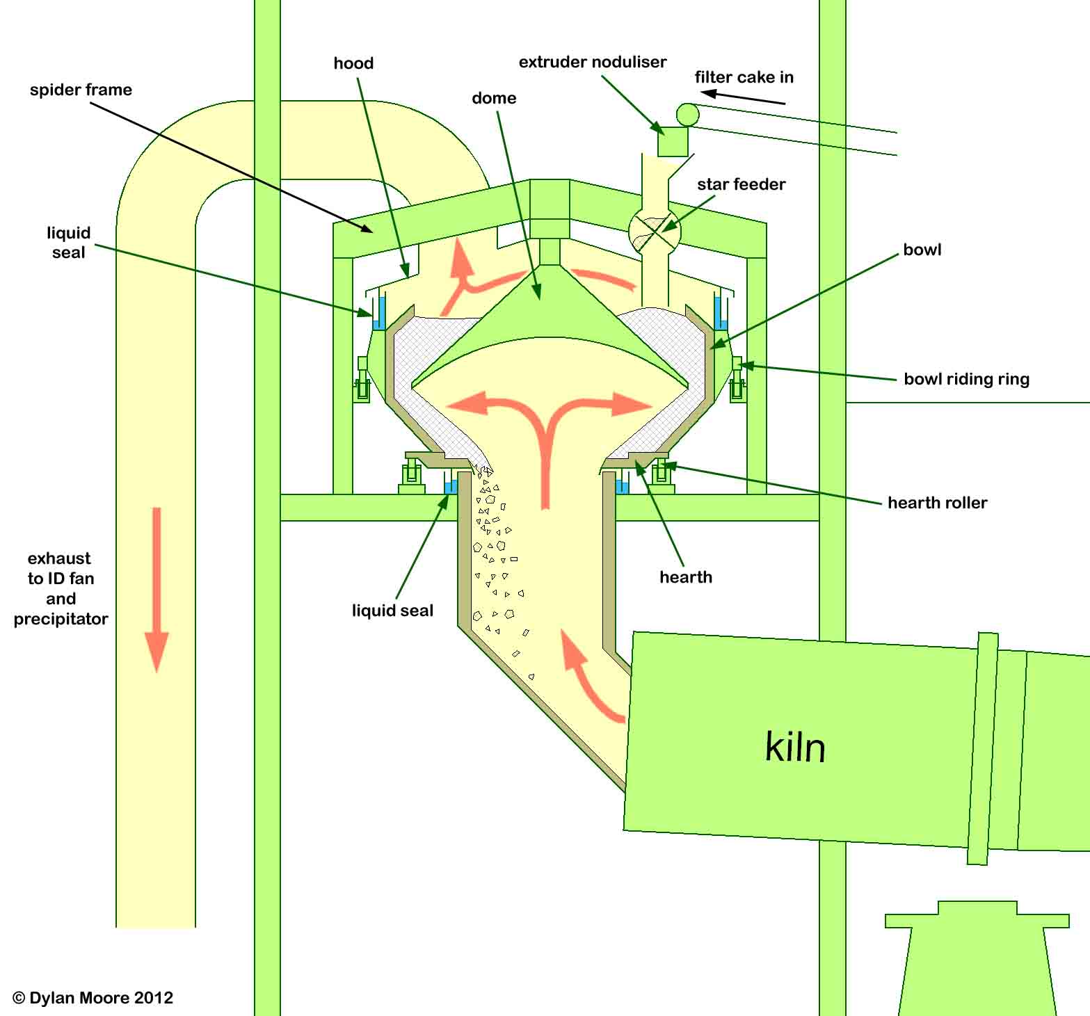
The preheater consisted of:
a rotating horizontal "hearth" surrounding the hot gas riser pipe outlet
a rotating bowl-shaped vessel above the hearth
a static hood over the bowl, connected to the exhaust fan
a dome structure suspended within the bowl that diverted the gas flow to the periphery.
Air-tight liquid seals linked the static and rotating parts. The annulus between the dome and the bowl was filled with filter cake nodules, the rotation of the bowl distributing the nodule bed. The hearth was concentric with the riser pipe, whereas the bowl was offset slightly, so the dried nodules were shunted off the hearth into the kiln as the bowl rotated.
The depth of the bed could in theory yield better heat exchange than - say - a Lepol grate, and the vertical arrangement allowed a leak-free design. But the combination of the bed depth and the odd shape of the gas path meant that large parts of the bed became "dead" and compacted, while the gas would find its way through whichever small part of the bed that was free. Although, particularly at Dunstable, clinker alkalis were very low, sulfate and chloride cycles between the preheater and kiln still caused blinding of the bed, as well as massive build-up on the dome and consolidation of the compacted cake. Although the deep, damp nodule bed was expected to minimise the dust content of the exhaust gas, both the Bevans and Dunstable installations had intractable losses of dust which was difficult to precipitate, causing major environmental problems at these urban sites.
Later Developments
In the 1970s, the energy crisis brought on a second look at semi-wet processes. In 1978, Southam A6 was modified with a Lepol grate fed with nodules extruded from pressed filter cake. This ran moderately successfully after solving alkali problems. In 1980, the purpose-built Rochester A6 was installed using the same process. A large kiln, this had the second-largest Lepol grate ever constructed. The fuel consumption was not particularly low, and the overall cost, including financing the extra capital of grate and presses, meant that the kiln was not much cheaper to run than a conventional wet process kiln. In 1982, Southam A7 was converted to take dry feed from a crusher/drier fed with filter cake, the crusher/drier being heated by kiln exhaust gas – a system similar to that used on Pitstone A5 dry process kiln much earlier. Finally, in 1983, kilns C1 and C2 at Shoreham and kilns A2 and A4 at Northfleet were converted to be fed with filter cake, without preheaters. This could be done relatively cheaply, but the overall energy balance of these kilns was no better than that of a well-run wet kiln. The heavy chain systems required to get adequate heat exchange produced huge quantities of dust, the re-cycling of which severely compromised the kilns’ operation.
A subtle problem with all the British semi-wet installations is that efficient, automatic filter press systems are extremely expensive, and so one of the standard rules of kiln system design - that all ancillary equipment should be over-designed compared to the kiln itself - was ignored. As a result, kiln operation tended to be periodically or permanently restricted by press throughput problems. The "pressability" of slurry is influenced by a multitude of subtle mineralogical effects, and sudden increases in press cycle time, or production of insufficiently stiff cake, are often difficult to diagnose, and even more difficult to remedy, except by installing more presses at great cost.
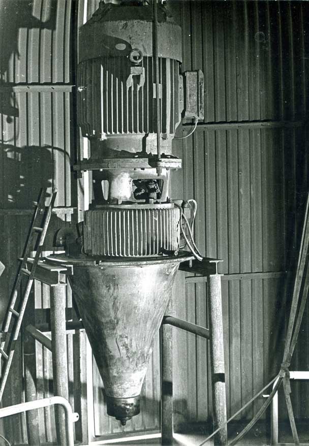 Picture: Peter Ellis. In the space above the drier chamber, a spare atomizer assembly. Slurry is fed into the conical section, and the wheel at the base expels it centrifugally. Above are the gearbox and the motor.
 Picture: Peter Ellis. This shows the Humber spray drier, viewed from the southwest. At the centre is the hot gas duct rising from the kiln hearth, at the outlet of which the spray wheel is located. Particles fan out from this into the 9 m diameter drier chamber, and either drop directly down the "legs" of the chamber or are caught by the cyclones attached to the sides. The elevator and conveyor to the right returned the dust from all three kilns to Kiln A3 feed chute.
 Layout of Polysius Slurry Dryer: "static" chains in green, moving chains in red.