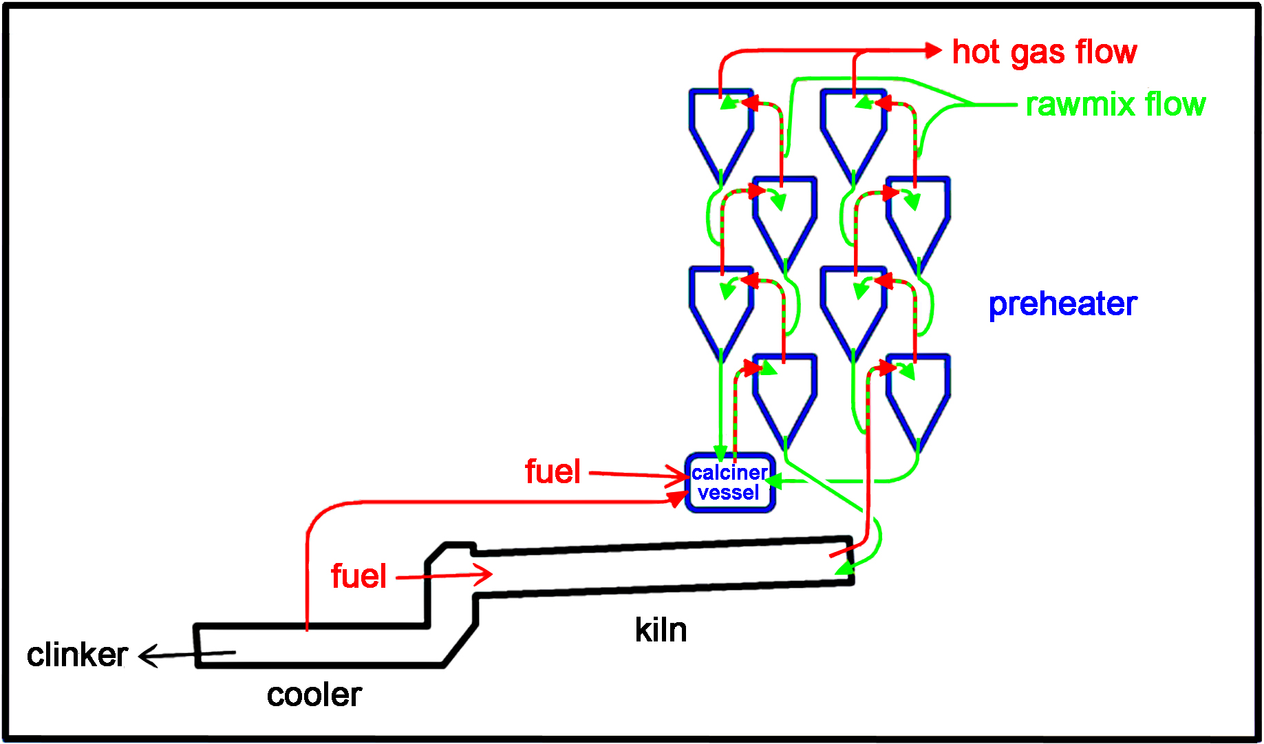
A twin-string four-stage air-separate precalciner kiln layout
This is one of an infinite variety of arrangements possible in a precalciner system, the common feature being the burning of part - and sometimes the large majority - of the kiln's fuel in the preheater in a vessel designed for that purpose.
Today, nearly all new kilns installed have precalciners. They represent the final improvement in efficiency, and hold out the prospect for nearly total elimination of heat wastage from cement kilns.
The precalciner system is a suspension preheater in which, in addition to the kiln flame, extra fuel is burned in the base of the preheater. The first kilns of this kind operated in Japan in the late 1960s. These systems allow more thermal processing to be accomplished efficiently in the preheater. This allows a greatly increased throughput for a given sized rotary kiln tube.
The idea of the precalciner emerged naturally during investigation of the ways in which suspension preheater systems could be made more thermally efficient. The main usage of heat in a dry process kiln is in the decomposition of calcium carbonate in the temperature range 650-1050°C. It was found that well-operated suspension preheaters could raise the feed temperature to around 750°C, at which the carbonates might be 10% decomposed. This led to attempts to increase the amount of decarbonation in the preheater by injecting extra fuel at its base. The provision of an aerodynamically designed vessel in which this could be done constituted the first precalciner.
There are two types: so-called “air-through” and “air-separate”.
In these, all the combustion air passes through the kiln. The velocity of the gases at the rear of any dry process kiln is a limiting factor on its output, since, above a critical velocity, powdery feed gets picked up and blown back out of the kiln. The air-through design is therefore limited in output in the same way as an ordinary suspension preheater system. Furthermore, by burning less fuel (for a given air-flow) at the main burner, the flame is diluted by excess air, and this cools the flame. These two factors therefore place a limit of around 25% on the proportion of fuel that can be burned in the preheater. This is sufficient to raise the degree of calcination of the feed entering the kiln from the 5-10% typical of suspension preheaters to around 40-50%.
Despite these limitations, air-though systems had the advantage that they could be relatively easily retro-fitted to existing kiln systems, and could be used in conjunction with the planetary coolers that were favoured in the 1970s.
In these, extra combustion air ("tertiary air") for the calciner is extracted from the cooler. This can only be done easily if a grate cooler is used. The design avoids the constraints suffered by the air-though design; the combustion air for the calciner by-passes the kiln, so that high gas velocity and flame dilution are avoided. The proportion of fuel that can be efficiently burned in the calciner rises to about 70% (for ordinary blended rawmix feeds). The degree of calcination of feed entering the kiln rises to around 90-95%, and this defines the 70% fuel limit - any more fuel will risk the formation of clinker in the preheater, and this must be avoided at all costs. This optimisation of thermal efficiency allows a large output to be produced by a relatively small kiln. The kiln solely performs the sintering process, for which the rolling action of the rotary kiln is indispensible.
A number of distinct advantages of air-separate precalciners has resulted in their almost universal use in modern cement plants. In addition to the large output obtainable, the separation of the clinker production process into distinct stages means that each can be separately controlled, solving a major operational problem that characterised all previous kiln designs. There is a small but significant improvement in fuel consumption, because the relatively smaller sized kiln loses relatively less heat from its shell.
Not all precalciner kilns are strictly speaking "dry process", since modifications have been devised allowing filter cake (Semi-Wet Process) or even slurry (Wet Process - e.g. Rugby and Tunstead) to be fed to the system. Naturally, the more water is added to the system, the higher is the energy consumption, but the flexibility of the precalciner arrangement at least allows this energy to be transferred with a minimum of collateral waste. The potential fuel efficiency of clinker manufacture is almost entirely defined by the nature of the raw materials, and the inherent fuel cost of wet raw materials - defined by the First Law of Thermodynamics - can't be ameliorated by process design.
As with conventional suspension preheater kilns, the gases leaving the top of the preheater are used for drying raw materials. Some heat is still wasted, because rawmills tend to run intermittently, since they are always designed with "overtaking capacity" to avoid restricting the output of the kiln. While the rawmill is stopped, the hot gas has to be run to waste, usually with injection of water in a conditioning tower. With this limitation, the number of cyclone stages used depends on the amount of drying capacity needed: if the raw material is very wet, a smaller number of stages is employed so that ample waste heat will be available. If the raw material is dry (and reliably so, year-round) then a larger number of stages can be used, minimising the amount of heat leaving the kiln system. Here, again, the number of stages that can be employed is limited by the escalating fan-power requirement offset against the diminishing returns from adding an extra stage, despite continual improvement in "low-pressure drop" cyclone design. In Britain, the maximum number of stages employed is six, at Padeswood.
It is not intended to treat these modern systems in any detail because
it is the policy of this website not to describe currently operating systems in detail in the public version of the site
the various systems are too idiosyncratic to describe on a common basis
much of the current technology is proprietary
excellent general-interest accounts can be found in equipment suppliers' websites.
 A twin-string four-stage air-separate precalciner kiln layout