1902 Newspaper Article
This was an article published in the Sussex Daily News on Wednesday 15th October 1902, as part of a weekly series which also included: Reason's Electrical, Brighton; Tamplin's Brewery, Brighton; the Burgess Hill Brick and Terracotta Works; Rope-making at Hailsham; Dolphin Soap Works, Kingston and Regent Ironworks, Brighton - all, incidentally, extinct in 1991. The article was re-printed as a publicity pamphlet by SPCC around 1911. A number of footnotes mentioned changes since 1902, and these are given in italics.
SUSSEX INDUSTRIES
No.2 - CEMENT MAKING: Sussex Portland Cement Company
The manufacture of Portland cement is a process with the details of which the public generally are probably quite unfamiliar. As a rule the idea of the uninitiated is that it has some relation to chalk, and perhaps one or two other substances. That the process of manufacture is on quite an elaborate scale, requiring complicated and perfectly adjusted machinery, many processes needing the most careful supervision, a great number of delicate chemical tests, and the employment of a considerable amount of skilled labour, is occasion for surprise to the majority of people. Yet this industry is one which should be of particular interest to Sussex, for it is this county which possesses two cement works of importance, where the process of manufacture is carried on by the aid of the very latest improvements. The history of Portland cement is in itself of much interest, but it is sufficient here to say that it is made, to use general terms, by the grinding together and calcining of chalk and clay. The name "Portland" was applied to it in consequence of the resemblance which the cement bore to the limestone found near Portland in England.
FORMATION OF THE SUSSEX COMPANY
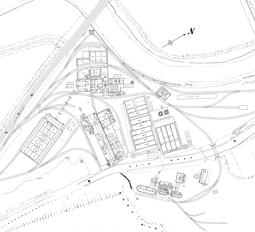
The Sussex Portland Cement Company was formed, and the construction of the Newhaven Works started in 1884 by Mr A. E. Carey, the then resident engineer of the Newhaven Harbour Works, and Mr A. J. Jack, another engineer, connected with the same works. The Newhaven works were erected at Heighton on a portion of the estate of the late Viscount Hampden, who took great personal interest in the undertaking and materially assisted by his influence and support in the early development of the Company's business. Valuable help was also rendered at the starting of the concern by the late Mr. George A. Wallis (then agent to the Duke of Devonshire), who was a director of the company up to the time of his death. These works, as originally constructed, were designed for an output of 300 tons per week. They were, however, increased from time to time, and are now turning out some 600 tons per week. At the close of 1897 the works of the old Shoreham Cement Company, situate at Beeding, were acquired, the output of these works at that time being about 100 tons per week. These works have been practically reconstructed since the Sussex Portland Cement Company took them over, and they are now capable of an output of 800 tons per week, making the total output of both works 72,800 tons per annum. The number of men employed on the two works is over 300, a large proportion of these men being housed in the Company's own cottages, erected adjacent to the works. The members of the present Board of Directors, viz:- The Hon. A. G. Brand, M.P., Mr. Edward Eagar, Mr. F. G. Courthope, Mr. A. J. Jack, and Mr. J. F. Plaister, have been associated with the management of the Company since it commenced active operations in 1886, and they are all resident in Sussex. Mr. Jack was appointed General Manager in 1887, which post he continued to hold until 1891, when he resigned and joined the Board, continuing to act as Consulting Engineer to the Company. Mr. Plaister, the present Managing Director (who had assisted in the management since the commencement of 1887), then assumed the control. A representative of the "Sussex Daily News" recently visited the Company's works both at Newhaven and Shoreham, and was shewn the processes adopted from first to last, beginning with the procuring of the raw material and ending with the despatch of the finished article.
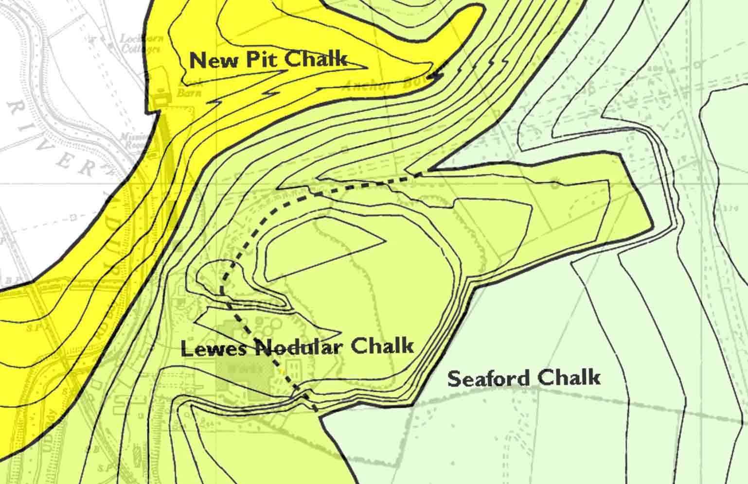
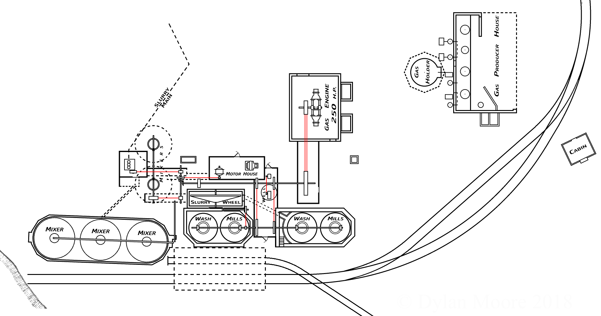
When the works at Newhaven were started in September, 1884, the downs sloped gently to the roadway. Since that time, no fewer than eight acres of chalk soil have been cleared, and where the hill side formerly declined gradually to the valley of the Ouse, it is now perfectly level ground. On the top of the hill, a tumulus once existed, and an old Roman brooch (now in the museum at Lewes) was found near this spot. The chalk, of course, is here in abundance and the other portion of the raw material, gault clay, is obtained by the Company from a pit at Glynde, the railway affording every facility for transit. There is an extensive face of chalk at Newhaven, the hill in one place having been cut right through. No less than 98 per cent of carbonate of lime is contained in the chalk here, and this a great advantage in view of the purpose for which the chalk is required. In order that night may not interfere with the cutting away of the hill side, a travelling electric light, capable of journeying along the whole face of the cliff, is used, its rays being directed upon any spot where work is going on. The proportion of chalk to clay is, speaking roughly, three to one. The chalk is brought whence it is cut to the washmill in trucks which run along a small railway. These trucks work on a hinge, so that the load is easily tipped, and the contents emptied into the mill's mouth. A similar course is followed with the clay. Inside the mill a process, quite terrifying in appearance, goes on. The mixture is churned and ground and stirred by harrows, while a small stream of water constantly flows in. The effect of the washing is to get an intimate compound, and to reject the useless matter, such as flints, which are not required. When the washing process has been duly accomplished the stuff is passed through a fine grating which stops the flints, &c., and allows the passage only of the washed chalk and clay, which from this point is technically called slurry. The latter then goes into a "mixer", where are left behind those small flints which have not previously been eliminated. From the "mixer" the slurry is "elevated" by a series of buckets on a wheel, and every bit is ground as small as possible between mill stones. In fact one of the most important stages in the manufacture of the cement is to get this stuff ground fine enough, though up to recent years this part of the process was considerably neglected in most of the English Works. The slurry has now to pass through a 180-sieve, which is a sieve containing 32,000 meshes to the square inch; and it is important that the residue should not exceed five per cent. As a matter of fact, the Company grind their residue to three per cent. Constant tests are made in order that this fineness should be secured. By means of powerful pumps the slurry is now conveyed to the drying floors, which are fitted with flues in order that the waste heat from the kilns, which adjoin them, shall pass over and under them, drying the slurry and converting it into what is technically designated "slip". As the slip dries, it is broken up and wheeled into the kilns, where it is deposited with alternate layers of coke.
TWENTY THOUSAND TONS OF COKE
The consumption of fuel by this method is about half a ton of coke to a ton of cement, and the quantity of coke consumed per annum is 20,000 tons. The fumes and moisture from the kilns are carried off from the drying floors by means of high chimneys. When the kilns are lighted, they are sealed up in front and at the bottom, and a fresh quantity of slurry is run on to the drying floors. Thus, while the kilns are burning, they are at the same time drying other floors of slurry. There is a range of 21 kilns, and the time a kiln takes to burn through and dry a floor is four or five days. The burning process, too, is most important, for it is necessary that the contents of the kiln should be burnt thoroughly, but neither over nor under burnt. If they are over burnt they are of no value at all, while under burnt material is of inferior quality, and likely to do harm in the work for which it is used. In consequence of this the kilns require very careful attention. After the stuff is burnt, the change in its composition has a corresponding change in name, and what was slurry now becomes clinker, the effect of the burning being to drive out the carbonic acid gas and to bring about chemical combinations of the lime and clay. All partly burnt stuff has to be carefully removed, and a special staff of men is engaged for this purpose.
Pamphlet footnote: Since the above was written, a Rotary Kiln plant of the latest type has been installed at the Newhaven Works.
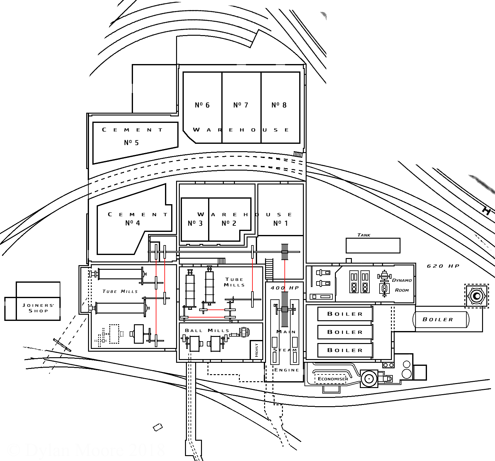
Trucks are run right into the mouth of the kilns, where they are filled, then they are taken by a tramway over a weighing bridge, where they are weighed and the weights registered. The clinker is then passed through two large crushers into a "hopper", which feeds the ball mills, consisting of drums half full of heavy steel balls, and the revolutions of which grind the clinker down to a certain degree of fineness. From the ball mills the stuff is passed through a sieve into a hopper, and thence into the tube mills, which finish this process by grinding the clinker into an impalpable powder. The last grinding is, of course, most essential and complete; and when the process is ended the cement will pass through a sieve, having 5776 meshes to the square inch, leaving a residue of no more than five per cent. This is the result of ordinary grinding, but the machinery now is so excellent that the cement can be ground to nearly any degree of fineness; indeed, the Company have a special specification, where it has to pass through a sieve with 32,000 meshes to the square inch, leaving a residue not exceeding ten per cent.
The pamphlet changed this to 15%! In modern cements, this quantity is essentially zero.
Formerly this grinding was done by mill stones.
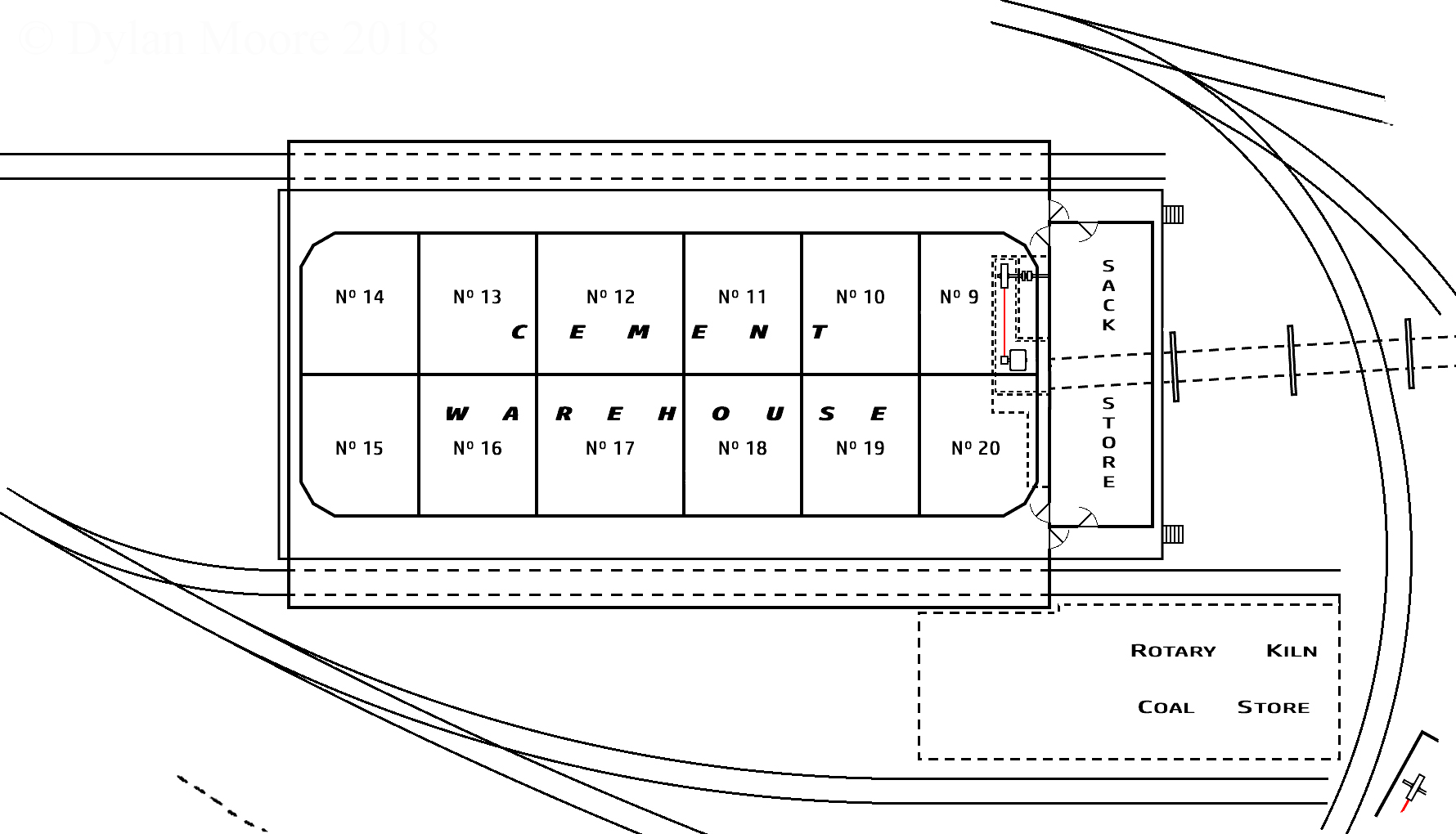
A STORE FOR 8,000 TONS
After passing through the tube mills the cement is elevated into an automatic weigher; thence into a conveying screw, which takes it the whole length of the store; and it is then dropped into bins, the object of which is to aerate it thoroughly before it is despatched. Bins are kept for various customers. The whole of the cement in each of these bins is tested daily as manufactured until the bin is full; and it is again tested as it is sent out. One advantage of this store (which is lighted by electricity), is that all the work therein is done under cover; and it is so large that there is no necessity to bag the material up until it is actually wanted. This again gives the cement the additional benefit of aeration. On either side of the store are lines of rails, and the trucks run up them under cover. As each truck is filled it is covered with a sheet. After this the trucks leave the works, and their contents are not touched until they reach their destination, every precaution being taken to ensure their arrival at the consumer's in a perfectly dry state. There is space for twenty trucks on each side of the store, and their total contents when full equal 200 tons of cement. With an efficient staff of men this quantity can be loaded in an hour. The storage capacity is 8,000 tons. The bulk of the Company's trade being home trade, the principal part of the packing is done in sacks, and there is a store in which the sacks are kept, but a certain amount is done in casks, and the Company have their own cooperage, where their casks are made.
THE MACHINERY
The engine house contains two compound condensing engines, one of 400 h.p. which drives the dry mill, and a 200 h.p. engine, which drives the wet plant. Adjoining there is an electric installation for the lighting of the whole of the works, and the driving of some of the machinery. The wear and tear of the machinery in all of the departments of cement manufacture is very heavy, and it is therefore most important that it should be maintained in first-class order and every little defect immediately remedied. In order that this shall be effected without delay of the gear being sent away the Company have their own staff of fitters and a large fitting shop, containing all necessary lathes, shaping machines, etc. This machinery is driven by electricity. The fitting shop is built entirely of concrete, and adjoining is the smith's shop. Before the company did away with the mill stones in favour of new dry grinding machinery they decided to put up an additional mill, on the most modern lines. The new mill is driven by a compound condensing engine of 250 h.p. of the marine type. The mills are all on one floor, and instead of feeding into a crusher, trucks are brought direct from the kilns into the elevator and are emptied direct into the ball mill. What follows then is practically the same as before, but afterwards the cement is brought into a belt conveyor, which has the double advantage of conveying the cement with the expenditure of less horse power than that necessitated by the screw conveyor, and of being open to the atmosphere, and thus aerating the cement as it is carried along to be dropped on to the screw which delivers it into the bins. A book is kept in each mill for recording the testing of the grinding, which is done every half-hour, sieves being specially provided for the purpose. This is quite independent of the ordinary testing in the testing rooms, each man being responsible for his own department. An automatic weighing machine is also used to see that the proper quantity is being sent through the mills, and the results are duly booked, so that there is little chance of a slip.
AN ELABORATE TESTING SYSTEM
The careful testing of the finished cement and the materials in the various stages of manufacture is imperative, and for this purpose a laboratory and testing room are provided where tests of every possible description are carried on daily by an efficient staff of chemists and assistants. In the laboratory the raw materials, viz., chalk, clay, coal, coke, etc., are constantly tested, and the chemists are also occupied in research work with the view of bringing about further improvements. Nothing is passed into the kilns until it is absolutely certain that the chemical combination is correct. Besides testing the fineness of the grinding of the chalk and clay as passed through the wet mill, a process is adopted to ascertain the carbonate of lime in the slurry; this is done half-hourly or hourly as may be required by means of a chemical apparatus called a calcimeter. These Sussex Works were about the first English Works to adopt this instrument, although its use has since become almost universal in the cement trade. This, like many other scientific processes, is copied from the Germans, whose methods the Sussex Portland Cement Company have been at pains to consider and where advantageous, adopt. After the cement is ground, daily samples of the manufacture are brought into the testing room for chemical examination, and are tested for fineness, setting time, specific gravity, weight per bushel, and breaking strain, also for soundness. The tests for breaking strain are of considerable interest. The cement is mixed with a certain quantity of water and forced into moulds, where it remains for twenty-four hours until thoroughly set. The briquettes thus formed are taken out of the moulds and are placed under water, and allowed to remain there for periods extending over two, six and 27 days, three months, six months, and twelve months. At the end of each of these periods the briquettes are taken out, and broken in the testing machine. The usual requirements of engineers at the present time are a breaking strain of 400 to 450 lbs per square inch after seven days. Of the briquettes, which our representative saw tested, one gave a breaking strain of 590 lbs after seven days, and another, after three months, failed to break at 1000 lbs.
THE MAKING OF BRIQUETTES
For practical purposes, it is the finely ground cement which is of the greatest value. To prove the value of the fineness of the cement it is made up into sand briquettes, the proportion being three of sand to one of cement, and it is very important that the consumer should see that he buys a cement that will give him a good breaking strain with sand briquettes. The breaking strain of a sand briquette required by the average engineer is 200 lbs per square inch after 28 days. The sand briquettes which have remained that time and which our representative saw broken gave breaking strains of 390 lbs and 470 lbs.
These values correspond to modern EN 196 compressive strength values of 18 and 23 MPa. The engineer would apparently accept 7 MPa. The British Standard for cement had not yet been published. Modern 28-day strengths are around 60 MPa.
More importance is attached to this test than to the neat cement test, but these sand briquettes require very careful making; as the comparative results obtained would be useless unless precisely the same conditions were observed for making each briquette, this necessitates the employment of special apparatus and an expert tester. Different times of setting are, of course, required for different purposes. For instance, drainage and sea works require fairly quickly setting cement, while for general work, the time required is longer; and the company naturally make a special point of suiting the requirements of their customers, their system being so perfect that they can prepare their cement to set in any time from twenty minutes to twenty-four hours. Circular pats of cement are tested for the initial and final set by means of a pointed instrument pressed downward by a 2 lb weight, the power which the point has of penetrating the pat giving the extent to which it has set. As a test for soundness, the pat is put on a piece of glass, placed under water, and watched for any signs of cracking, or of coming away from the glass. This test is carried out in fresh water, but there are other tests by means of sea water and boiling. From first to last the results of all the tests are registered. Every process is kept recorded and has been for years past, the results forming quite a library. If a consumer wishes to know the result of the test of any particular supply it can be furnished at once, the tests being registered with the name of the consumer opposite them. A series of tested briquettes is also kept, which can be referred to if necessary, and the Company also have a sample pat of every day' s manufacture since the works were started.
In the reconstruction of the Shoreham Works, which are situated at Beeding, the Company were able to allow for many improvements which it was found impossible to adopt at Newhaven, and here the processes are carried out upon what are recognised as absolutely the most modern lines. An exceptional advantage of the Shoreham works is that they are situated on the banks of the river Adur. The result of this is that the Company are able to despatch their cement and receive coal, coke, and other supplies in their own barges by water. The clay for use in the works is brought by barge from the Company's own freehold clay-pit at Horton, about three miles from the works. The unloading is effected by means of a steam crane. One of the cement stores is built on the wharf so that the cement can be loaded into the barges direct from the store. There is a considerably larger face of chalk here, but it is cut out and conveyed to the works on a tramway in exactly the same way as at Newhaven. There is a gas-making plant for driving the gas engines; and on the side of the cliff from which the chalk is being cleared a new washing plant and wet mill, which will be driven by a 250 h.p. gas engine is in course of erection. The process followed as to the chalk and clay is similar to that at Newhaven, but the washing and mixing plant is more elaborate owing to the more modern methods of burning, which require different methods of washing to achieve the same chemical result. At Shoreham there are two washmills and two mixers instead of one of each, so that if one breaks down the other is ready to go on. The new wet plant which is being put up will also be duplicated. The present plant is not sufficient to deal with the larger burning plant without working night and day, and it is the Company's intention to avoid this if possible.
THE GERMAN SCHNEIDER KILN
The drying process is practically the same as at Newhaven, but it was found that so much heat was being wasted in the kilns, that another drying floor was constructed over the top of the kilns on which stuff can be dried to feed German Schneider continuous kilns. This kiln was invented by a German, from whom it takes its name, and is not only economical in the matter of fuel consumption, but also burns more regularly and efficiently than the old type. The slip is taken off the top of the chamber kilns by tramway and fed into the Schneider with layers of coke in a similar way to that adopted in the chamber kilns; only in this instance the quantity of coke required is much less and the kiln is never stopped for drawing, for as fast as fresh stuff is put in to burn the finished material is being removed. There are altogether fourteen chamber kilns and two Schneider kilns. Each Schneider kiln turns out 100 tons of clinker per week, whereas the ordinary chamber kiln only deals with from 25 to 30 tons per week. The process at Shoreham is completely automatic from first to last, the stuff being handled as little as possible.
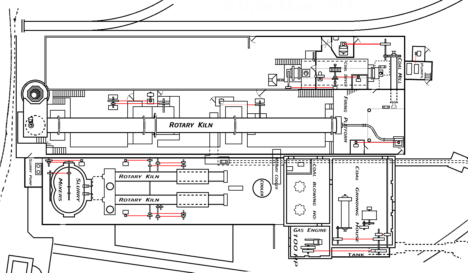
AN IDEA FROM AMERICA
Having found out what were the methods employed on the continent the Company turned their attention to America, where they found the rotary kiln system in vogue. By this system, which the Company adopted, it is possible to dry and burn the cement and completely manufacture it in 2½ hours, whereas by the old system it takes from ten days to a fortnight. The rotary kiln is fed with the slurry by long pipes leading from tanks, the feed being controlled by one man. The kiln itself is a long inclined cylinder lined with fire bricks, which is made to revolve slowly. The slurry is fed into one end, and as it travels to the further end it gradually dries and burns, eventually dropping out of the lower end of the tube in the form of clinker; but instead of being in large lumps it is in small lumps the size of beans. This kiln ensures perfect burning of the clinker, and there is little or no half-burnt stuff. The burning is done with finely powdered coal, which is blown into the kiln by means of a fan and ignited immediately it enters the kiln. As the clinker falls from the kiln it is taken up in an elevator and dropped into a cooler, whence it is conveyed automatically to the mill to be ground. Coal fuel, being used instead of coke, enables the manufacturer to be more independent, as the coke market is subject to more heavy fluctuations than the coal market, besides which the supply of coke locally, owing to the introduction of water gas, is not nearly so large as it was formerly.
GAS AND ELECTRIC POWER
The whole of this plant is driven by electricity, and it is so admirably arranged that it requires only two men to look after it, one man for each kiln. The Sussex works were the first in England to adopt this system and make it a practical success. Since the plant was started at the Shoreham works it has been running continuously with scarcely a hitch. To start the plant the Company had an advantage over other English cement makers in securing the services of men from Denmark, who had been working a similar plant in that country, which was then practically the only place where lengthy experience of drying and burning slurry with rotary kilns could be gained.
Pamphlet footnote: Since the above was written, a further rotary kiln plant has been installed, capable of an output of 1000 tons per week.
In the works is a 100 h.p. gas engine which drives the coal grinding drying plant for the rotary kilns, in itself quite an elaborate process. The main engine which drives both the wet and dry mills is of 400 h.p.; and the electric plant is driven by a 60 h.p. Parson's steam turbine, and two compound condensing engines. One of the cement stores is similar to that at Newhaven, and there is an additional store nearing completion. When completed the two stores will have accommodation for 9,000 tons. It is possible, in the two stores, with an efficient staff working simultaneously, to load 260 tons per hour, all the work being done under cover. A similar arrangement to that at Newhaven is effected in regard to the trucks, which are brought under cover alongside the bins. As at Newhaven a fitting shop, laboratory, testing room, and competent staff of chemists are provided. There is also a staff of draughtsmen kept, the Company designing all their own works, mills, etc. Both the Newhaven and Shoreham Works are connected by sidings with the London, Brighton and South Coast Railway, which affords every facility for the rapid dispatch of the cement by rail and also for shipment by the Railway Company's wharves at both ports.
SOME GREAT UNDERTAKINGS
The important works supplied by the Company bear ample testimony to the high quality of their cement. To the Newhaven Harbour Works over 17,000 tons were supplied during the construction of the breakwater, which is a fine example of monolithic construction and considerable additional quantities have since been supplied to the Harbour for minor works and repairs. The Company's cement has always proved eminently reliable and suitable for sea works, and has been used for large concrete groynes at Brighton and Hove, also for the Marine Parades and Sea Walls at Brighton, Hove, Bognor and other South Coast watering places, the most recently completed work of the class being the important Sea Defence Works at Seaford and Newhaven. Supplies have also been made to important Dock and Canal Works such as the Manchester Ship Canal, Tilbury and Southampton Docks, and the Alexandra Dock at Newport, Mon. The British Admiralty, when obtaining supplies of cement, specify particularly to tensile strain, fineness, specific gravity, and chemical analysis, and provide for the inspection of the cement at various stages. The Company have supplied the dockyards at Portsmouth, Devonport, and Pembroke Dock; also the Admiralty Works at Portland and Guernsey, and have given every satisfaction. The large blocks of Naval and Military Barracks constructed at Portsmouth during recent years have taken over 6,000 tons. Railway Works also account for large supplies of cement, and the Company has held the annual contract to the L. B. and S. C. Railway for 13 years. The modern application of concrete to drainage foundations, and flooring, has caused an increasing consumption of cement in every locality. Such buildings as the Hôtel Métropole (sic), Brighton (for which 2,000 tons were supplied), large Retort houses and Gas Holder Tanks at important towns, together with Drainage Works and Sewer Outfalls take a considerable portion of the Company's output. The Company has held the important annual contract of the Brighton Corporation for 14 years, and also those of Eastbourne, Folkestone, Torquay, Lewes, Plymouth, and other towns for varying periods. For the Manchester main drainage they supplied over 5,000 tons, and this year they are sending thousands of tons to the same Corporation for important Sewerage Works. Other important jobs now being supplied are the new East Sussex County Lunatic Asylum at Hellingly, the Glasgow main drainage, and the contract, extending over six years, for barracks at Tidworth, Salisbury Plain. This last is one of the largest and most important building contracts ever given out in this country, and the Company have arranged to supply the whole of the cement required.
THE COMPANY AND THEIR EMPLOYEES
One necessary outcome of the situation of the works at Newhaven and at Shoreham has been the springing up of miniature towns in both neighbourhoods. In both cases the works are practically isolated, and it has been with the object of having the bulk of their working population on the spot that the Company have erected rows of cottages for their occupation. Besides the cottages there are houses at both works for the works managers, the latter overlooking the works and thus commanding the whole situation. Some years ago a Sick and Provident Fund was started by which the men receive 12s. a week during illness and doctor's attendance when required; funeral allowances are paid to the widow or other relatives on the death of a workman, and to a man on the death of his wife. Near the Newhaven Works is a commodious Recreation and Reading Room with stage at one end. This stage can be used when entertainments are organised, and at other times can be partitioned off to form Committee rooms. Non-alcoholic refreshments and tobacco are supplied; there are billiard and bagatelle tables, and illustrated newspapers are provided without any expense to the men. During the winter months, entertainments are arranged by a committee elected entirely among the employees, and these are held in this Recreation Room. Moreover, the Company have at their own expense laid out a recreation ground for cricket and football. At the Shoreham works a mess room is provided for those men who come considerable distances. It will thus be seen that the Company have continued the enterprise and forethought they have displayed in prompting their business schemes to the people who work for them, and who benefit accordingly, and it is very probable that this consideration for their workmen has not been the least of those influences which have helped the works to attain their present position.
Pamphlet footnote: Since the foregoing article was written the company have acquired the old established Works of Messrs. Hooper and Company at Southampton, and the total combined output the works are now capable of is 125,000 tons per annum.
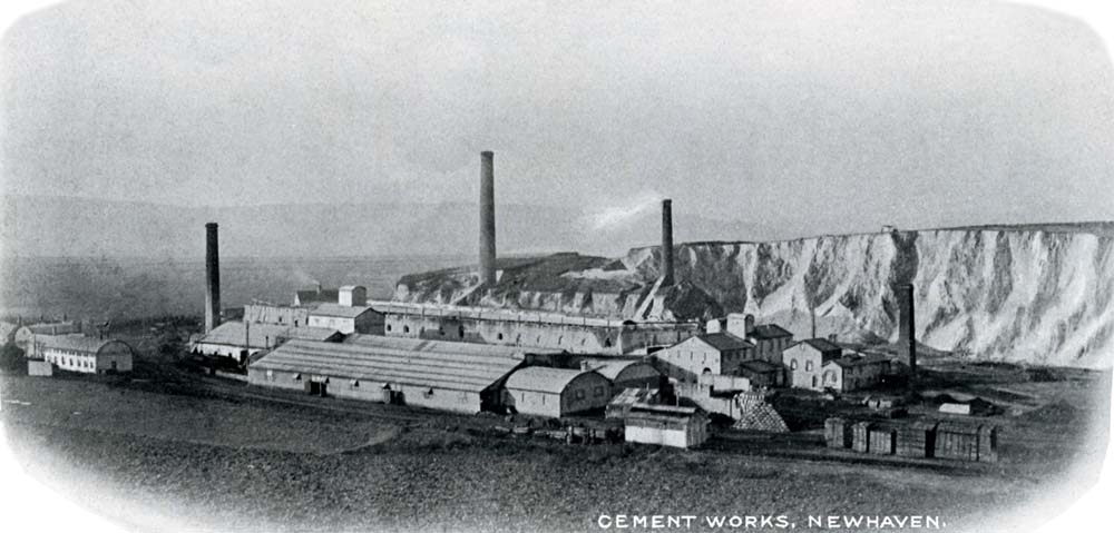
 View
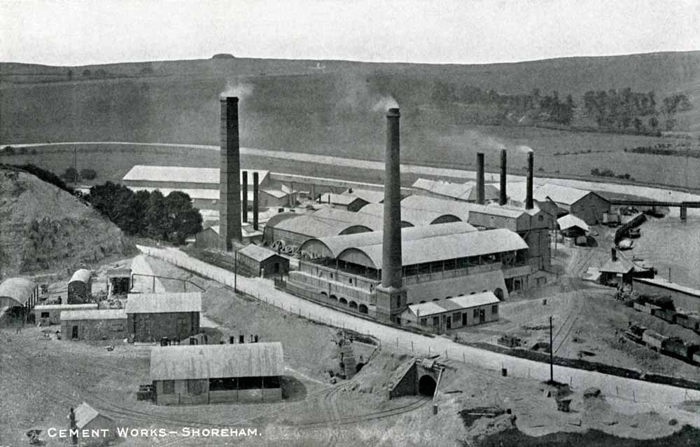
View 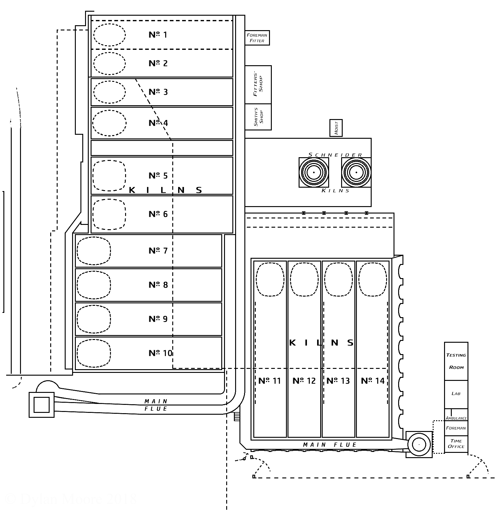

 Kilns 1 & 2: picture courtesy of Chris Down