
The following is a transcript of an anonymous article that appeared in The Engineer, CXVII, pp 310-312 (March 20, 1914).
The cement plant near Claydon, Suffolk was completed in 1914 as a replacement of Mason's old-established Waldringfield plant. The old plant had used old-fashioned bottle kilns with the thin-slurry process, and using chalk brought from the Thames. Moving 17 km inland afforded an opportunity to use local chalk, and to abruptly update to rotary kiln technology. Despite the consultancy of Maxted & Knott, the plant was not of the highest technology, and although the company installed two further similar-sized kilns in 1923 and 1939, it could not compete with the industry leaders and so could never afford to upgrade to better technology and work practices. The company was finally acquired by Blue Circle in 1948, and the plant was systematically upgraded. Clinker production finally ceased in February 1999.
Values of imperial units (as of 1914) used in the text (alphabetical order): 1 acre = 0.40468424 Ha: 1 ft = 0.30479947 m: 1 gallon = 4.5460756 dm3: 1 HP (horse-power) = 0.7456998 kW: 1 inch = 25.399956 mm: 1 psi (pound-force per square inch) = 6.89478 kPa: 1 ton = 1.01604684 tonne: 1 yard = 0.91439841 m.
A NEW CEMENT WORKS NEAR IPSWICH.
We recently had an opportunity of inspecting, by the courtesy of the proprietors, the cement works at Claydon, near Ipswich, which have lately been started by Mason's Cement Company. These works have been erected to the designs of Maxted and Knott, Limited, of Hull (Note 1), and they possess many features of interest.
 |
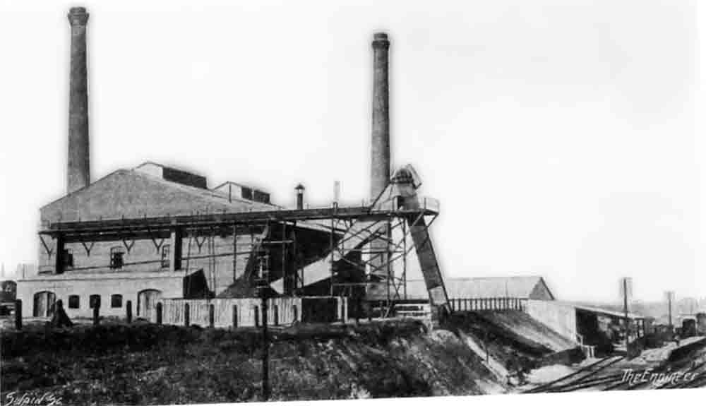 |
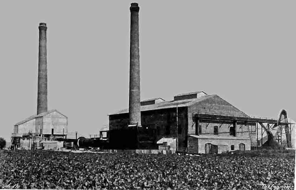
| Fig. 1 - General view, from the southwest. | Fig. 2 - Rail siding and coal elevator, from the southeast. |
The locality was evidently intended by nature for the erection of cement works. The geological formation is most curious. Chalk and clay of exactly the composition necessary for the manufacture of high-class cement actually lie in juxtaposition in the same quarry, in one part of which there is a vertical face of chalk with the clay actually butting up against it. One may stand in a given place and take a spade full of chalk from one side and a spade full of clay from the other. The formation throughout the area is not quite the same as this, but chalk and clay of precisely the correct character will always be found in close proximity the one to the other. Hence it is only necessary to mingle the two constituents in the correct proportions in order to produce a slurry which, when burnt and ground, will be transformed into Portland cement of the desired quality (Note 2). As a matter of fact, it is Messrs. Mason's custom always to mix the slurry with the clay slightly in excess of the correct quantity, and to add the requisite amount of chalk at a later stage of the manufacture, as will be explained in due course. This method of procedure has been found to work out exceedingly well.
The quarry is situated at a distance of some 800 yards from the site chosen for the erection of the works. The reason for this distance is that the works as built are situated alongside the main line of the Great Eastern Railway between Ipswich and Norwich, from which a siding has been run on to the site for the ready delivery of coal and dispatch of finished cement. Having regard to the cartage which would have been necessary had the works been erected near the quarry, such a course was manifestly out of the question. But the problem arose of how best to convey the raw materials from where they were mined to the works. It was finally decided to mix them on the site and to pump the resulting slurry to the works. Accordingly, two wash mills have been constructed at the edge of the quarry, and the chalk and clay are brought to them in small tip wagons running on narrow-gauge lines. At the present moment, while the workings are still quite close to the surface, it is only necessary to propel these trucks by hand, but when the excavations grow in depth some sort of power haulage will be needed, and we believe that the form employed is to be an electric winch.
The wash mills are of the ordinary type with revolving mixing arms, and call for no comment. They are driven by electric motors, which obtain their current from overhead conductors running from the power-house at the works, which will be referred to later. One of the motors is of 35 horse-power, and the other of 45 horse-power. The latter motor, in addition to driving its wash mill, has to work the pump for forcing the slurry towards the works. The slurry as it is formed flows into a sump below the pump. The pump is of the single-plunger type, and the plunger is 7in. in diameter. It has been found convenient to do the pumping in two stages, and, accordingly, a small brick building has been erected about midway between the quarry and the works, and contains another pump driven by a motor of its own. From this point a 5in. cast iron pipe laid on the ground runs direct to the works.
The slurry on arrival is delivered into the suction sump of a single ram electrically driven pump, and is forced up to a height of some 20ft. above ground level, where it is delivered into a wet tube mill, which is also motor-driven, and in which the slurry is reduced to the requisite fineness. The delivery from the tube mill is into a channel, whence the slurry can be diverted into any one of three slurry mixers. These are circular tanks 20ft. in diameter and 11 ft. deep (Note 3), and they form quite a feature of the whole installation. Projecting upwards from their bottoms are several pipes arranged at regular intervals through which compressed air can be forced. The result of this series of blasts of air in each tank is that the whole contents of the tanks are most thoroughly mixed. It is from these tanks that the samples are taken for the analyses, which are continually being made while the tanks are being filled. We have mentioned above that the slurry as mixed at the quarry is purposely made to contain an excess of clay, and it is in the mixing tanks under consideration that chalk is added in such quantity as to make the relative proportions of clay and chalk correct. This method of air mixing appears to be performing its functions extremely well, and some wonderfully even results in the final cement are being obtained. Each air blast pipe is provided with a small stop cock, so that as many pipes as is desired may be in blast at one time, and the quantity of air they are delivering varied at will (Note 4). For containing the chalk required to establish the correct proportions in the slurry a small tank is mounted just over the mixers (Note 5), and chalk slurry may be made to flow into each of the three tanks as and when directed by the chemist.
It is customary to fill the mixers completely before drawing off any slurry for the purposes of manufacture, and doubtless this course is wise from the point of view of the regularity of the final product. From the mixers the slurry, which is now ready to be burned, is allowed to flow into a sump from which it can be lifted by one or other of two chain bucket pumps to a height of some 35ft., where it is delivered into a small circular reservoir situated immediately over the feeding end of a rotary kiln. This reservoir is also provided with pipes for delivering compressed air right down to its bottom, so that the slurry may always be kept thoroughly mixed and of the same consistency throughout. From the reservoir the slurry may be allowed to flow by gravity into the kiln at the correct rate.
 |
There is one rotary kiln, which is 41 m.—say. 134ft. 6in.—long, in the portion devoted to the drying of the slurry and the burning of the clinker, while there is a further length of some 14ft. at the delivery end, where the clinker is cooled by the incoming current of air, which itself is heated in the process (Note 6). The general diameter of the kiln is 2 m.—6.56ft.— but for a length of some 30ft. near the delivery end this diameter is widened out to 2.4 m. —7.87ft . —so as to form a clinkering zone or combustion chamber. The kiln is carried on three sets of thrust rollers in the usual manner, and is revolved by an electric motor working through gearing on to a toothed wheel keyed to the outside of the drum.
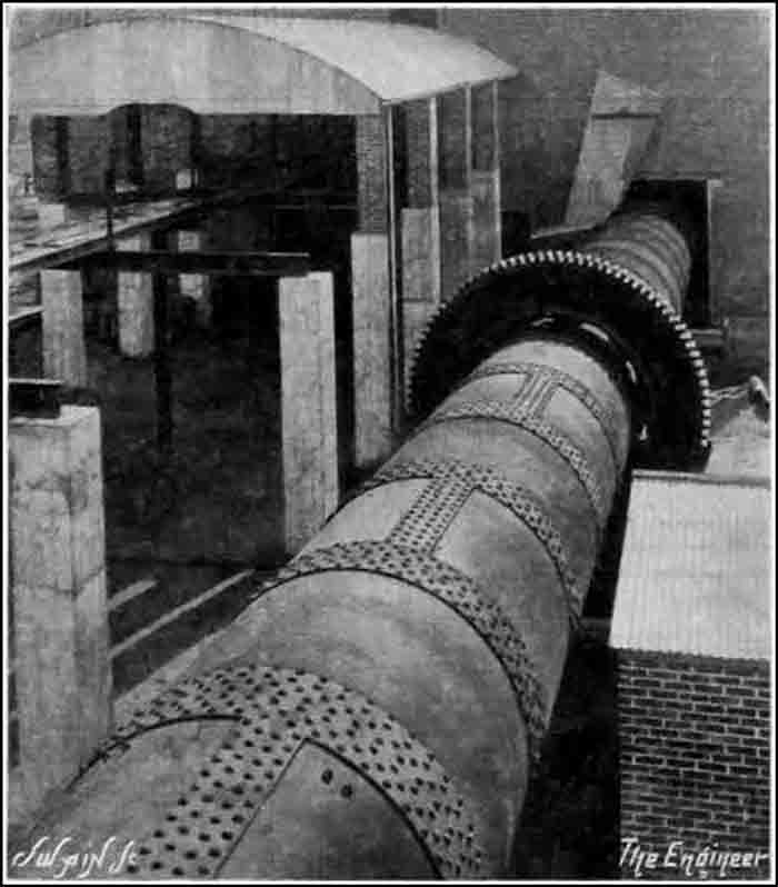 |
| Figure 6: Rotary kiln: view from the slurry tanks. The incomplete building to the left is the clinker store. The brick building to the right, not shown on the plan, houses the kiln drive motor. |
In many cement works where rotary kilns are at work it is customary to pass the heated clinker as it comes from the kiln through a separate inclined tube through which a current of air is made to pass, the clinker being cooled and the air, which is afterwards passed into the kiln, being heated at the same time. In some instances the cooling of the clinker is carried to such an extent that the burnt material can readily be held in the hand as it emerges from the cooler. At Claydon, as we have explained above, the cooling of the clinker is brought about in an extension of the kiln itself, and, though undoubtedly the clinker is delivered with a higher temperature than is the case when a separate cooler is used, and hence there is some waste of heat in this manner, yet there is undoubtedly less loss of heat from the air itself since it has not to be transferred to the kiln from a separate cooler, but passes into the interior after travelling over clinker the temperature of which becomes higher and higher till it is actually the same as that of the clinker in the kiln itself (Note 7). The air and gases from the kiln are discharged into a chimney after being passed through a smoke and dust chamber in the customary manner.
In order that the delivery end of the kiln may be used for cooling the clinker, as just explained, the coal dust used for firing is introduced by means of a pipe which is sufficiently long to project beyond the cooling portion (Note 8). Saving for this, the kiln is fired in just the way that is usual with rotary kilns—that is to say, the coal dust in the correct quantity is blown into the kiln by a current of air produced by a fan driven by a motor. The coal before being ground is thoroughly dried in a special drum, which is some 40ft. long and 2ft. 9in. in diameter. This is mounted in a brickwork casing, so that the heated gases from a separate fire may be allowed to circulate round it, and it is revolved by means of 15 horse-power motor working through belts and gearing. On issuing dry from this drum the coal is taken up by an elevator and deposited in a storage hopper arranged above a grinding mill. This mill is of the tube type, but is not just an ordinary tube mill (Note 9). It is 23ft. long by 4ft. in diameter for two-thirds of its length, and is divided into two sections. The first of these—about a third of the total length—is of rather greater diameter than 4ft., and contains steel balls. In this section the coal is reduced to a fairly fine powder and then passes into the next section—which contains pebbles—for the grinding to be completed. The coal cannot pass from one section to the other until it has been fairly finely ground. The mill is carried on two sets of thrust rollers, and is revolved by belting from the main shaft in the engine-room, which we shall describe a little later on. The ground coal when discharged from the mill is lifted by an elevator and deposited in a hopper in the kiln firing room, from which hopper it is drawn and discharged into the kiln as already explained. The coal dust hopper has a capacity of some 1870 cubic feet (Note 10).
Before going on to describe the storage and grinding of the clinker and the storage, packing, and despatch of the finished cement it will be convenient at this point to describe the power plant for running the works. This has been supplied by Richard Garrett and Sons, Limited, of Leiston, Suffolk, and consists of two of this firm's well-known Garrett superheated steam, self-contained engine, boiler, and superheater plants. These plants are of considerable interest, and we therefore propose to describe them in some detail. Each engine has been designed for a continuous load up to 255 brake horse-power and for a temporary overload of 300 brake horse-power, with a working steam pressure of 190 lb. per square inch and at a speed of 170 revolutions per minute. The engines are two-cylinder compounds. Our readers are acquainted with the general form of this engine. as we described a single-cylinder engine of this type in our issue of February 4th, 1910. The engine and boiler are combined, the cylinders being fixed on the top of the boiler. which is of the fire-tube type, has a grate area of 19.7 square feet, and is fitted with a Wilkinson internal cold feed-water heater, which Messrs. Garrett have found greatly assists the circulation. In an extension of the boiler casing is a Garrett superheater which, in the particular engines which we are describing, imparts 223 deg. of superheat to the steam. Both cylinders of the engines are controlled by piston valves. These valves take steam at the centre and exhaust at the ends. The governor is of the centrifugal type, keyed on the fly-wheel, and it works on the high pressure valve through a rocking gear. The low-pressure cylinder simply has a fixed excentric (sic) keyed on the crank shaft. We understand that the engines were guaranteed to govern to 2 per cent. within the limits of no load and full load, and that they actually do better than that in practice. Each engine is fitted with a jet condenser and Edwards' air pump, while for feeding purposes there is a mechanical pump as well as an injector. The guaranteed coal consumption with Welsh coal or its equivalent is 1.3 lb. per brake horse-power hour at full load (Note 11). We are informed that the consumption at ¾ load is 1.47 lb. and at ½ load 1.55 lb. The water consumption, as found during trials on the site, was 9.8 lb. per brake horse-power hour.
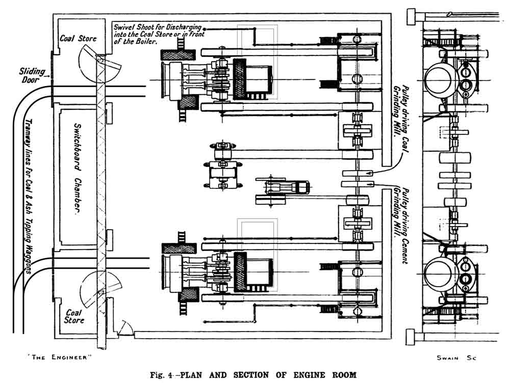 |
Each engine, as shown in Fig. 4, has two fly-wheels, each 7ft. 6in. in diameter by 16in. face, both of which act as pulleys, and drive by belt a line of main shafting, the speed of which is 220 revolutions per minute. This shafting is provided with two friction clutches arranged one on each side of four further pulleys, one of which latter drives by belt and gearing the coal grinding mill already described, while the remaining three drive respectively a direct-current generator, an air compressor, and the clinker grinding mill, which will all be referred to in due course. These clutches have been provided in order that either engine or both of them together may drive on to the shafting.
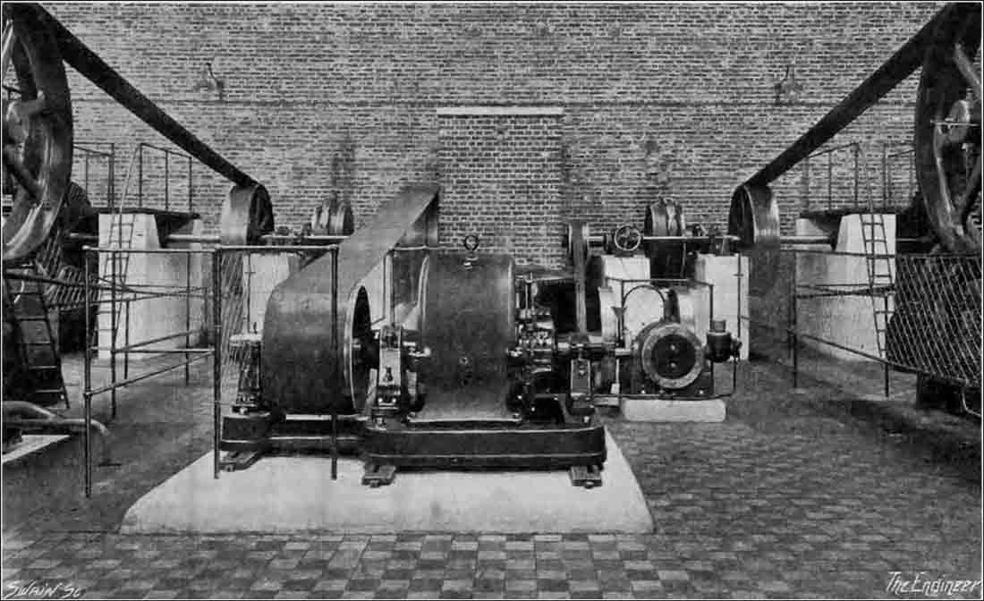 |
| Figure 5: In the engine room. Between the engines are (left) the main DC generator and (right) the compressor. The shaft passes through the brick enclosure at the rear which houses the pulleys for the coal mill and finish mill, which are beyond the wall. |
The coal necessary for feeding the boilers, which it will have been understood from what has already been said form a part of the engine, is brought into the building in the following manner:—Arranged at the side of the siding from the railway which has already been mentioned is a receiving hopper into which coal can be discharged direct from railway wagons. Dipping into this hopper is a bucket elevator, which raises the coal to a screw conveyor which runs horizontally at a level of about 28ft. above the floor of the engine-room and at right angles to the centre lines of the engines with its own centre line 16ft. 3in. from the fronts of the furnace doors. At the rear of each engine and immediately beneath the conveyor is a coal store, and by means of a pair of swivelling shoots the coal can either be discharged into one or other of these stores or on to the floor of the engine-house in front of the furnace doors. It should also be mentioned that outside the building there has been formed a covered coal store into which the conveyor can be made to discharge when desired. A narrow-gauge line with two branches, one running into the engine-house opposite the end of each engine, has been laid, this line providing both for obtaining coal from the store and also for the discharge of ashes. We must not forget to state also that the coal conveyor can also be made to discharge coal into a hopper arranged directly above the coal drying drum. The whole coal-handling installation has, in fact, been very cleverly laid out (Note 12).
The other machinery in the engine-room consists of a direct-current generator having a capacity of 200 kilowatts at 500 volts; an air compressor designed to deliver 400 cubic feet of free air per minute at a pressure of 30 lb. per square inch; a motor generator for delivering current at 200 volts for lighting purposes; and two small pumps for circulating the condensing water. These call for no special mention. The water as it comes from the condensers is pumped to the top of a cooling tower supplied by Richardsons, Westgarth, and arranged over a concrete tank close by the engine-room.
As no water supply was available, it was found necessary to sink a bore-hole, which was carried down some 200ft. from the bottom of a concrete lined well, which is itself 23ft. deep and 3ft. 6in. in diameter. The ordinary level at which the water stands is rather over 23ft. from the ground surface and the water is pumped from the bore-hole by means of an electrically driven pump fitted in the well. In order to avoid the expense of putting down another borehole at the quarry for mixing the slurry, some of the water obtained from the well is pumped to a small tank adjoining the wash mills. It is intended at a future time to erect at the quarry a large concrete tank at such an elevation that all the water required through the works may be supplied by gravity with only one pumping. Before use in the boilers the water is treated in a softener supplied by Wm. Boby.
We can now proceed to trace the progress of the clinker when it is discharged from the kiln. It is, first of all, delivered into the hopper of a bucket elevator, which lifts it to such a height that it can be either diverted and fall by gravity into a storage hopper over the cement grinding mill, or else on to a conveyor running out of the building at right angles and passing over a covered-in clinker store. This store has a concrete floor measuring about 100ft. long by 25ft. wide, and is capable of housing some 1500 tons of clinker. There is an opening leading into the building again at the floor level, this opening leading to a shoot connecting with the hopper of an elevator so that when desired clinker can be taken from the store heap and shot into this hopper so as, in its turn, to be lifted to the storage hopper over the cement grinding mill. This mill, though rather larger, is constructed on exactly the same lines as the coal grinding mill—that is to say, it consists of two portions, the first with the larger diameter, but lesser length, containing steel balls, and that with the small diameter and greater length, containing pebbles (Note 9). In this case, too, the cement cannot pass from one section to the other until it has attained a certain degree of fineness. It may here be mentioned that both in the coal grinding and cement grinding houses there is a noteworthy absence of dust, some exceedingly efficient dust collectors having been installed.
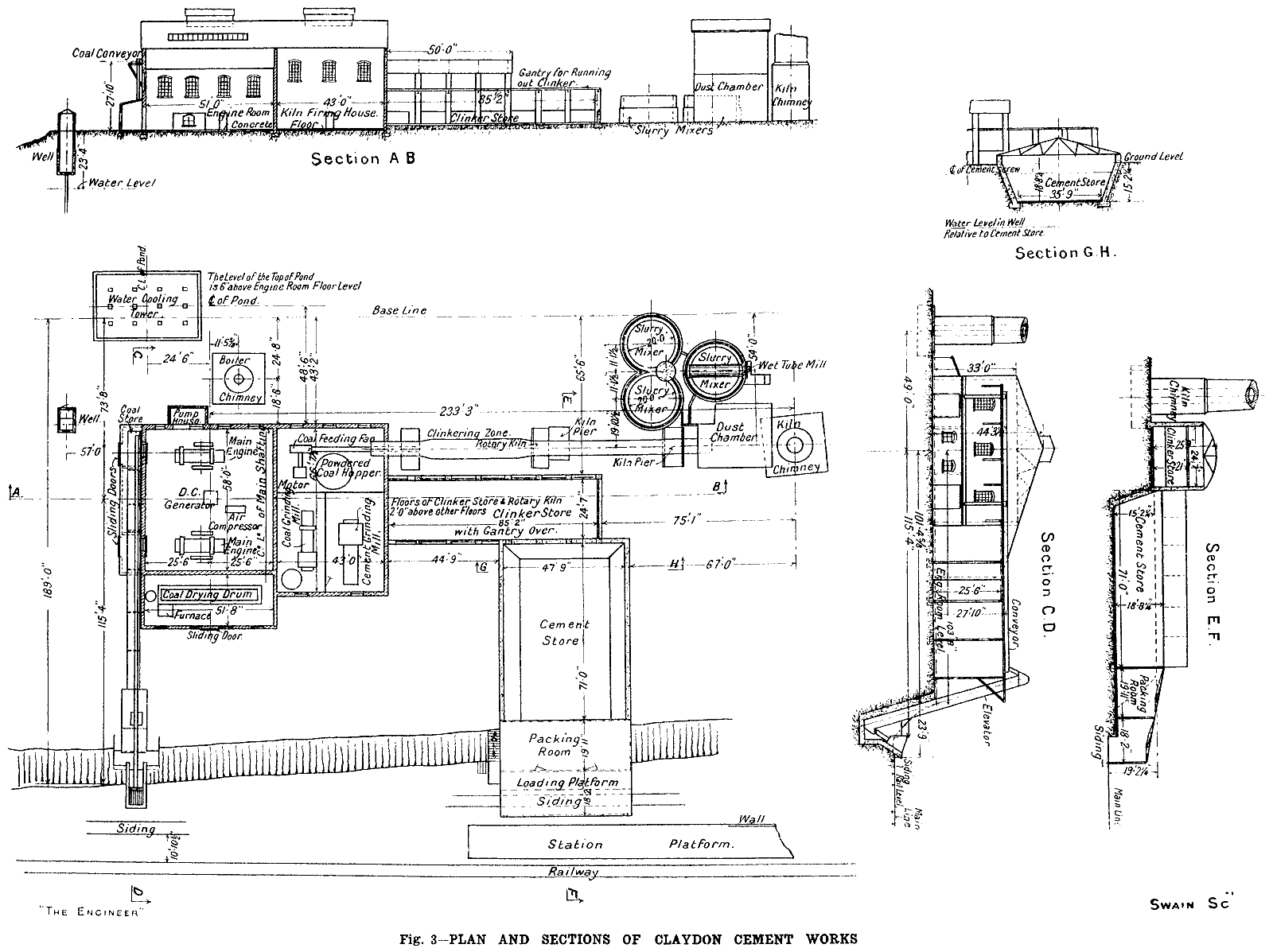
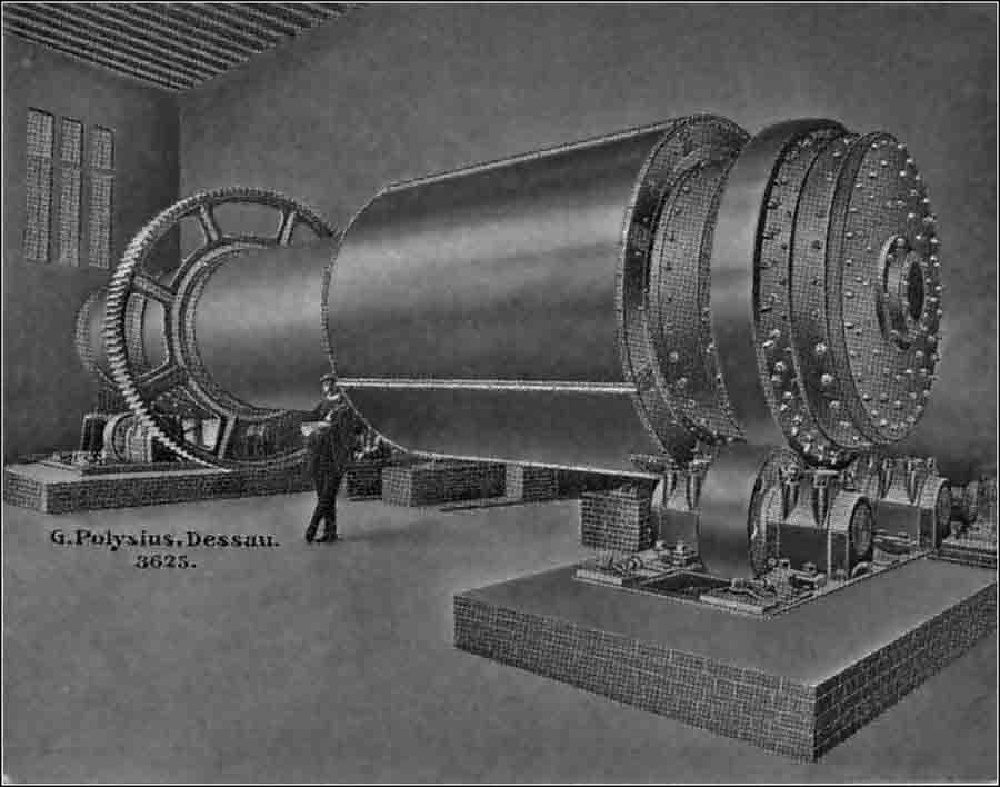
The finally ground cement is delivered by means of a conveyor into a cement store, which is a concrete building capable of containing some 2000 tons. Adjoining it is a packing room, the floor of which is at the same level as a platform erected alongside the railway siding already mentioned. An examination of the accompanying drawings will show that a great deal of ingenuity has been exercised in the general lay-out of the works, the material in its various stages travelling on from point to point without going backward. We may add that the whole of the machinery—with the exception of that of which we have already named the makers, and of the electrical machinery, which, with the exception of the switch-board made by Ferranti Limited, was supplied by Bruce, Peebles and Co., Limited—was installed by the G. Polysius Eisengiesserei and Maschinenfabrik of Dessau. We may add that the electrical equipment includes eighteen motors of a total of 250 horse-power (Note 13). The factory is capable of turning out 400 tons of finished cement per week.
A few facts concerning the cement itself will doubtless be of interest. To begin with, the analysis of a typical sample as carried out by Mr. D. B. Butler, of 41, Old Queen-street, Westminster, is as follows (Note 14):—
| Water and carbonic anhydride | 1.48 | |
| Insoluble residue | 0.37 | |
| Silica | 23.50 | |
| Alumina | 4.91 | |
| Oxide of iron | 2.27 | |
| Lime | 65.65 | |
| Magnesia | 0.73 | |
| Sulphuric anhydride | 0.04 | |
| Alkalies and loss | 1.05 | |
| Total | 100.00 |
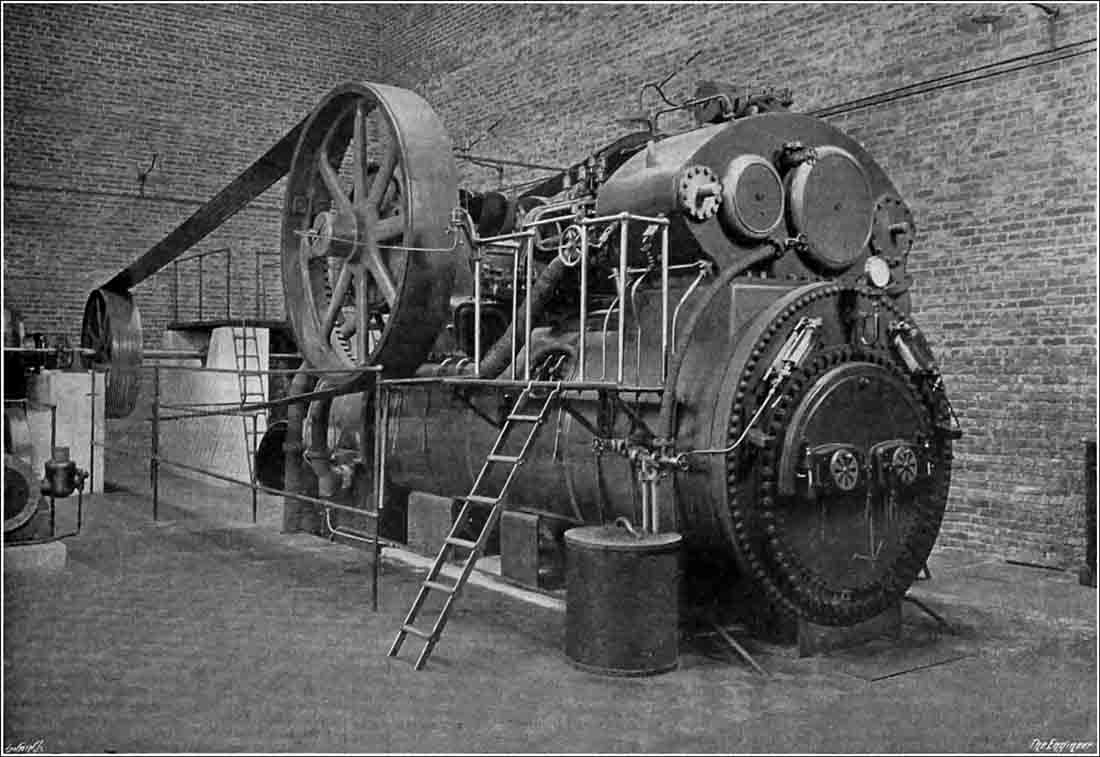 |
| One of the two Garrett engines. |
Masons kilns 1 and 2, in addition to their poor cooling arrangements, also had little in the way of inlet end heat exchange. At installation, they probably had channel "lifters" but these would quickly cake up and/or burn out, so that the plant settled down to living with exhaust gas temperatures in the region of 400-450°C. In 1931 waste heat boilers were introduced, supplying supplemental steam to the existing power plant. An article in Engineering described this. Similar installations were introduced at a few other plants, typically with similarly early, inefficient kiln designs. These included Cliffe, Rugby and experimental installations on one of the A-kilns at Swanscombe and at Beddington.
The waste heat boilers were subsequently removed when grid power was installed. The main power house was put out of action with the destruction of the stack in the 1941 bombing, and although the stack was rebuilt, it was never used, suggesting that at least a temporary grid supply was laid on at that time. The kilns remained inefficient, although they were somewhat improved by installation of chain systems following the Blue Circle takeover, and were finally shut down in 1966.
Waste Heat Boilers for Wet-Process Cement Kilns
The recovery of the waste heat from the gases of cement kilns operating on the wet process, presents difficulties on account of the low temperature of the gases issuing from the kiln, these being considerably cooler than is the case with kilns running on the dry process on which waste gas boilers have been installed for some time (Note 16). That the problem is not an insoluble one, however, is shown by the successful heat-recovery plant recently installed by Messrs. Spencer-Bonecourt, Limited, a subsidiary of Messrs. Babcock and Wilcox, Limited, Farringdon Street, London, E.C.4, at the works of Messrs. Masons Portland Cement Company, Limited, Claydon, Ipswich. The plant, which is illustrated in the accompanying Figs. 1 and 2, consists of a Spencer-Bonecourt patent high-velocity boiler with a dust settling chamber, containing a superheater at the inlet end and an induced-draught fan, discharging the waste gases into a brick stack, at the other.
The boiler (Note 17) is of the horizontal type, 7 ft. 6 in. in diameter by 12 ft. 3 in. long, containing two nests of tubes 1½ in. in internal diameter, the total heating surface being 3,200 sq. ft. The gases pass straight through the tubes, there being no retarders or baffles. The principle adopted in the Spencer-Bonecourt high-velocity boiler is that of setting up turbulent flow in the gases, which is effected by a calculated proportioning of the cross-sectional area and length of the tubes with respect to the volume and temperature of the gases, so that the velocity of flow is considerably in excess of the critical speed.
This critical speed, as was demonstrated in the classical researches of Osborne Reynolds on the flow through tubes, is the point at which a stream-line flow breaks up into a progressing mass of curling eddies, and by ensuring, in the design of the boiler, that it is constantly exceeded, intimate molecular contact between the gas particles and tube surfaces is maintained, with the result that each molecule imparts its sensible heat by actual contact effect. That the principle works well in practice is shown by the results obtained, for the data for which we are obliged to Messrs. Masons Portland Cement Company. The induced-draught fan (Note 18), which draws the gases through the tubes, maintains a negative pressure of 5 in. water gauge at the fan inlet, i.e., at the boiler outlet. At the time, the figures now quoted were recorded, the fuel burnt in the kiln amounted to 1,960 lb. per hour, and was ordinary slack coal, pulverised of course, having a calorific value of approximately 12,000 B.Th.U. per lb. (Note 19). The actual evaporation in the waste-heat boiler was 3,690 lb. per hour. The feed water being 55 deg. F., the evaporation from and at 212 deg. F. works out to 5,055 lb., with a corresponding rate per lb. of kiln fuel of 2.58 lb. of steam, or per square foot of heating surface of 1.57 lb. The steam pressure was 195 lb. per square inch, with a temperature, saturated, of 386 deg. F. The temperature of the gases in the superheater chamber, i.e., at the boiler inlet was 723 deg. F. (Note 20), and their temperature at the boiler outlet was 437 deg. F.. The temperature of the steam leaving the superheater was 650 deg. F. A comparison of these temperatures will show that a high degree of efficiency of extraction was reached. This, measured as a percentage of the total heat extracted by the boiler, between the limits of inlet-gas temperature and boiler water temperature, is very nearly 85 per cent., i.e., (723 - 437) / (723 - 386) × 100 = 84.87. It must be remembered, of course, that the fuel had already done useful work in the kiln, which was working at an output rate of 60 tons of clinker per day. The resultant steam was, therefore, generated at no other cost than that of the power required for the fan, and the interest on the capital cost of the boiler plant. On the other hand, as this steam is used in connection with other boilers for generating the electricity used in the works, the overall fuel costs for this latter purpose are considerably reduced.
 |
| Figure 1: Boiler side view - kiln to the right |
The power required to drive the fan cannot be said to be high, only 19.5 h.p. being necessary to draw the gases through the kiln, flues and boiler, and to ensure that the velocity through the tubes of the latter is high enough to maintain turbulence. The low power consumption is assisted by careful design of the boiler system as a whole, losses due to change of direction, eddying in the chambers, &c., being reduced to a minimum. In addition, infiltration of air is guarded against, all possible inlets between the kiln and the fan being effectively sealed. There is, therefore, no differentially increasing volume as the gases proceed towards the fan. The actual lay-out of the plant will be clear from the figures. The settling chamber containing the superheater is seen at the right of Fig. 1. It is provided with a sliding damper, so that the gases can be by-passed direct to the chimney for the purposes of boiler overhaul, &c. The chamber is of steel, lined with combined insulating brick and firebrick, and the boiler inlet casing is, in addition, lagged with 85 per cent. magnesia composition. Inspection doors and a hopper bottom for dust withdrawal are incorporated. The superheater is of the " Unit " type with detachable elements. A Babcock and Wilcox "Diamond" soot blower, calorised and of the "valve-in-head" type, is fitted on the boiler inlet casing, so that it serves for cleaning both the superheater and the boiler tubes. In connection with the latter, it may be mentioned that the small circles appearing on the end of the boiler in Fig. 2 do not represent the tubes, but are inspection holes so pitched that a flexible rod may be inserted for cleaning the groups of tubes in the immediate vicinity of each of them.
 |
| Figure 2: Boiler end-on view - kiln beyond |
The boiler is designed for a blowing-off pressure at the safety valves of 200 lb. per square inch. Standard Dewrance and Babcock and Wilcox mountings are fitted together with a Trist "Thermofeed" automatic feed regulator. Convenient platforms give access to all the mountings. The induced-draught fan is of the " Sirocco " type made by Messrs. Davidson and Company, Limited, Belfast. It is direct driven by a pipe-ventilated motor made by Messrs. English Electric Company, Limited, Stafford and Rugby. The control gear was supplied by Messrs. Brookhurst Switchgear, Limited, Chester. As the atmosphere of a cement works is usually more or less dust-laden from the clinker-grinding operations, the ventilating air to the motor is passed through a filter. This is most readily made out at the right of Fig. 2, and was supplied by Messrs. Wellman Bibby Company, Limited, Victoria Street, London, S.W.1. The fan discharges directly into the base of the original brick stack.
Masons was taken over by APCM in 1948, and the new owners immediately set about converting it from a small and inefficient plant with a local market into a reasonably modern plant that could fit into their national supply strategy. The initial modifications were done on a low budget, retaining the existing plant while improving its efficiency with more effective working methods, and supplementing these with a second hand kiln and finish mill. Final uprate to the best wet process efficiency of the time took place in the 1960s. The first stage was described in a publicilty handout in 1954, subsequently repeated in Cement and Lime Manufacture, 27, Sept 1954, pp 67-71.
Extension of Mason's Cement Works, Suffolk
When Mason's cement works at Claydon, Suffolk, started production over forty years ago its capacity was 20,000 tons a year. Additional plant was installed and in 1948, when the works was purchased by the Blue Circle group, the annual output was about 50,000 tons. Improvements to the existing plant were then carried out (Note 21) which resulted in an increased capacity of over 10,000 tons in 1949. Extensions have now been completed and the capacity is over 175,000 tons a year.
The clay is obtained about one mile from the works. It is boulder clay of the glacial period, and differs from most other clays used for cement manufacture in Great Britain in that it contains about 45 per cent. of CaCO3 in the form of hard nodules of pure chalk embedded in the clay (Note 22); this reduces the additional amount of chalk required. The clay is excavated by a mechanical face-shovel and transported to a 120-h.p. washmill which rotates at 24 revolutions per minute and washes the clay at a rate of 40 tons per hour. The slurry from the washmill has a water content of 55 per cent. (Note 23) and is pumped through a 6-in. pipe by one set of 12-in. diameter plunger pumps, with strokes of 15 in., a distance of about 3500 ft. to storage tanks near the chalk washmills.
The chalk washmills are situated in the chalk quarry, which is about half a mile from the works. The chalk is excavated by a face shovel at a rate of 80 to 100 tons per hour. It is then transported about 300 yd. and tipped into a rough washmill of 30 ft. diameter, rotating at 13 revolutions per minute, driven by a 170-h.p. motor. Here the clay is added to the chalk. After passing through 1.6-mm mesh sieves the slurry flows to a secondary mill of 23 ft. diameter driven by a 120-h.p. motor rotating at 24 revolutions per minute. This mill is lined with screens with holes of 0.75 mm diameter.
From the secondary mill the slurry is pumped a distance of 3000 ft. by two sets of high-pressure plunger pumps of 10½ in. diameter and 20 in. stroke through an 8-in. pipe to three correction tanks (Note 24). In the correction tanks the slurry, with a moisture content of 41 per cent. (Note 25), is corrected for chemical composition before it flows to the kiln-feed tank. From this tank, in which it is kept agitated both by air and mechanical means, the slurry is pumped to a spoon-feed at the back end of the kiln.
The Kiln.
The kiln is 231 ft. long by 8 ft. 6 in. diameter, enlarged to 10 ft. diameter in the burning zone (Note 26). It is supported on five cast-steel tyres and is driven by a 100-h.p. motor. The kiln has a maximum speed of 1.3 revolutions per minute. Its weight, when fully loaded, is about 600 tons. The kiln is fired by a No. 18 Atritor which is capable of drying and producing pulverised fuel at a rate of 12,000 lb. per hour.
Air for combustion is obtained by a Keith Blackman induced-draught fan, which rotates at 400 revolutions per minute, is driven by a 100-h.p. motor, and is capable of supplying 70,000 cu. ft. of air per minute at a temperature of 450 deg. F. This fan exhausts the kiln gases through a flattened-tube type electrostatic precipitator of similar capacity. The precipitator operates at 60,000 volts, and reduces the dust content to 0.4 grain per cubic foot at normal temperature and pressure before the gases pass to the reinforced concrete chimney which is 200 ft. high. The clinker passes through a rotary cooler 82 ft. 6 in. long by 6 ft. 4 in. diameter, where its temperature is reduced to about 140 deg. F (Note 27), before being delivered to a 12-in. continuous-bucket elevator and an 11-in. conveyor which conveys it to the main store. The main clinker store is served by two overhead travelling cranes of 5 tons capacity which distribute the clinker to the grinding mills.
Clinker Grinding Mills.
There are two clinker grinding mills. One mill is 7 ft. 3 in. diameter by 34 ft. long and is driven by a 700-h.p. auto-synchronous motor, through reduction gears, at 20.5 revolutions per minute; this mill has an output of about 12 tons per hour. The other mill, 6 ft. diameter by 36 ft. long, is driven by a 550-h.p. auto-synchronous motor at 26.5 revolutions per minute and has an output of about 9 tons per hour. Gypsum is added to the clinker as it is delivered to the mill. The cement is delivered, through air-slides, to a 7-in. Fuller-Kinyon pump which is capable of transporting 30 tons of cement per hour through a 5-in. pipe a distance of 500 ft. to the storage silos.
Storage Silos.
The four silos are of reinforced concrete. They are 85 ft. high by 30 ft. diameter, and have a total capacity of about 9000 tons. Cement is extracted from the base by air-slides and screw conveyors, which deliver to a hopper immediately above a Daylor four-spout packer. This machine is capable of packing 60 tons of cement per hour in 1-cwt. bags, which are conveyed by retractable conveyors to road vehicles. Arrangements are also made for delivering loose cement from the silos.
Water is obtained from a well in the former power house, and a reinforced concrete reservoir with a capacity of 70,000 gallons has been constructed. Electric power is purchased. The supply is 11 kV, and is transformed to 3 kV and 415 volts. The total power requirement of the new equipment is 3000 h.p., of which 1860 h.p. is on the 3 kV. supply and 1140 h.p. on the 415 volts supply. Maximum demand is about 2250 kVA with a load-factor of about 80 per cent. and a power-factor corrected to 0.96 lag.
NOTES
Note 1. Maxted and Knott began as a consultancy nurtured by G & T Earle, and Maxted functioned as permanent retained consultant to that firm until angrily ousted by A C Davis, who rightly regarded the curious relationship as deeply suspect. Maxted dealt mainly with Polysius as a source of practical knowledge, but as WWI approached, he transferred his allegiances to Edgar Allen, who were new entrants. Allen accordingly supplied Masons kiln 2, to an identical design to the Polysius kiln 1.
Note 2. Such daft accounts of geology are a picturesque feature of the cement industry to this day. Initially amusing, they become irritating after the umpteenth re-telling. The geology at Great Blakenham is typical of that throughout much of East Anglia, with Upper Chalk overlain with glacial deposits - in this case Boulder Clay. The top of the chalk is an irregular erosion surface, undulating and criss-crossed with deep gullies, all of which are filled with the glacial material. The Boulder Clay, consisting of material bulldozed from the rocks of Eastern England by advancing ice, necessarily contains a large amount of chalk, both as "boulders" and in finely-divided form. The two raw materials at Masons have typical composition (% dry basis):
| Chalk | Clay | |
|---|---|---|
| SiO2 | 2.49 | 39.51 |
| Al2O3 | 0.51 | 8.71 |
| Fe2O3 | 0.31 | 4.37 |
| CaO | 53.42 | 22.08 |
| MgO | 0.31 | 0.85 |
| SO3 | 0.14 | 1.48 |
| LoI925 | 42.59 | 20.63 |
| Na2O | 0.08 | 0.22 |
| K2O | 0.04 | 1.69 |
The mix typically contained 30-35% clay.
Note 3. With a capacity of 97 m3, these each held 88.6 tonnes of dry rawmix - enough to make 54 tonnes of clinker, or about 16 hours kiln run. Clearly, this was by no means a generous capacity, only just enough to get through a weekend, if all three were magically made chemically correct by Saturday lunchtime!
Note 4. As mentioned later, the compressor used for this had a free-air capacity of 400 ft3/min (0.189 m3/s).
Note 5. The tank (according to the plan) was only about 8 ft diameter, so perhaps 10% the volume of a blending tank. It would have to be filled with pure chalk slurry pumped to the plant down the same line, perhaps during "running down" of the washmills at the end of the working day. For the tank to cope, the ex-quarry slurry must have 0-10% excess clay - a tall order considering the lack of any chemical control at the quarry.
Note 6. The kiln was (as always with Polysius) metric, and the writer makes a valiant attempt to give the dimensions, but gets it all wrong. The article gives no explicit drawing of the kiln, but it looked like this:
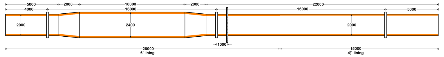
Note 7. This kiln and the identical kiln 2 continued in operation until 1966. While the cooling zone might have worked to some degree if the kiln was not being "pushed", flat-out operation, and the inevitable shortening of the firing pipe, resulted in typical clinker exit temperatures around 900°C, and by the 1960s temperatures were well over 1000°C. Some of these "integral" coolers were modified with van der Werf cold air injectors, but not so here. In addition to its high temperature, the clinker must have been poorly quenched.
Note 8. Such long, cantilevered firing pipes were the main weakness of the "integral" cooler - if lifters were used to achieve reasonable cooling, the pipe had to be protected from cascading clinker - or, as here, the clinker simply cooled, slowly and inefficiently, by radiation, exposing the pipe to high temperatures.
Note 9. A Polysius "Solomill" or similar. This was an early attempt to combine the "ball mill" and "tube mill" functions. In this case, the ball mill design with peripheral discharge was retained. The wide section was not an enlarged grinding chamber - it was a reservoir in which the peripherally-discharged fines were collected before being scooped into the second chamber centre inlet.
 |
| Polysius Solomill. |
Note 10. 53 m3, of capacity perhaps 30 t - enough for 32 hours run.
Note 11. 1 lb/BHP-hour = 0.168966 kg/MJ. So for a coal with 31 MJ/kg, the thermal efficiency is 14.7% at full load, 13.0% at ¾ load and 12.3% at ½ load.
Note 12. Evidently a great deal of shovelling went on.
Note 13. This represents a regression. Plants were being installed by 1914 with all drives electrified, albeit with home-generated power. Here the eighteen motors are:
|
Note 14. It will be noted that the cement is not "adulterated" with gypsum. The initial setting time is a short 45 minutes, and the cement was probably only saved from flash set by water addition, coarse grinding and an extremely unreactive clinker. No doubt this situation didn't last long. The "alkalis and loss", as with other analyses of the time, was not a determined quantity - it was just a balancing term. The alkalis were in fact probably very low. The other minor oxides together made up less than 0.5%.
Note 15. The corresponding values in modern EN 196 compression testing are 8 MPa at 7 days and 16 MPa at 28 days.
Note 16. No British dry process kilns had them. This refers to American practice. Dry process kilns could have exhaust temperatures of 700°C, providing high-grade heat. The inefficient Masons kilns were unrepresentative of wet process kilns in general, since many had exhaust temperatures below 300°C.
Note 17. Throughout the article, the installation is referred to in the singular, although some accounts suggest that boilers were fitted on both kilns, and even on Kiln 3 when it was installed in 1939 (although the latter was chained). A complication at Masons was that the kilns were in a fanned-out arrangement, with a common firing floor, but with feed ends and stacks about 30 m apart. It's not clear which kiln this was on, and the later history of the installation(s) is also very hazy.
Note 18. Previously, the kilns had operated only on stack-draught. A rough estimate of the gas flowrate at the mean gas temperature (316°C) is 18 m3/s, so to produce a fan inlet suction of 5" water gauge (= 1243 Pa), the power transferred to the gas is 22.4 kW. Compare the fan power of 19.5 HP = 14.5 kW (the balance presumably provided by the stack suction) so this fan can have had no positive effect upon kiln production, and in fact probably slowed it down, until a bigger fan was put in.
Note 19. This gives us a snapshot of actual kiln performance. The fuel mass flowrate is 21 tons/day and the fuel calorific value is about 26.78 MJ/kg (nett). The kiln clinker output is later given as 60 tons/day, so the coal consumption rate is 35% on clinker, representing an energy consumption of 9.37 MJ/kg.
Note 20. Given a modest 5% inleak at the back-end seal, this equates to a kiln exit temperature of about 758°F (403°C).
Note 21. .Improvements consisted mainly of installing commercial kiln refractories instead of the home-made clinker linings previously used, thus improving run-times, by chaining the kilns and removing the waste heat boilers. The plant had been connected to grid power during the war, and there was no need for on-site generation.
Note 22. It should be emphasised that this was not a marl; the carbonate took the form of hard nodules in a soft clay matrix, and the reduction of these remained a major technical problem throughout the life of the plant. The Boulder Clay overlying the Chalk in the area was deposited by ice sweeping south-eastwards from the Midlands, bulldozing Middle Jurassic clays from what is now the fenlands, followed by chalk from the Chiltern ridge.
Note 23. The clay slip moisture content was reduced to 40% in the 1970s, using sodium silicate and soda ash as additives.
Note 24. The correction tanks were the original Polysius kiln feed tanks. The addition of one 66 ft storage basin for kiln feed was not generous, giving only 54 hours run with four kilns.
Note 25. Slurry moisture remained in the range 40-42% until 1970, when the use of additives reduced it, and by 1977 it was below 30%. The Boulder Clay is particularly suitable for this - no other chalk-based plants achieved this low level.
Note 26. This was the pre-WWI Burham Kiln 1, which had stood idle since 1938. An extra 30 ft. rear section was added and chains were used.
Note 27. The other kilns did not have rotary coolers, and Kiln 4 was installed like them near ground level, so the cooler had to be put in a deep trench underneath.