Stokes' Cooler
A rotary cooler consists of a slightly inclined tube of similar construction to a rotary kiln, placed at a lower level than the kiln so that the clinker leaving the kiln can fall directly into the upper end of the cooler. Ambient air enters at the other end. The upper part of the cooler, because of the high temperature of the clinker, is brick lined, while the lower part is usually provided with scoops or "lifters" that pick up the clinker and cascade it through the air-stream.
The earliest rotary cooler described is in Stokes' patent of 1888, and a prototype may well have been installed on the kiln at Arlesey. He says:
In order to produce the required temperature in the furnace I prefer to use what is known as the "regenerative system" in which the air is heated previous to combustion, either by contact with the issueing (sic) hot clinker, the passage of the air being in the contrary direction to that of the hot clinker; or by the passage through regenerative chambers, or parallel flues, of well known construction, instead of the cooling drum aforesaid.
Stokes' drawings show a cooler 38 ft long and 2'3" diameter (the kiln was 28×5), lined for two-thirds of its length with 4" brickwork, while the rest has "projecting shelves" for lifters. If the kiln had worked (which it most certainly didn't) the cooler would have been very effective. In the ensuing 80 years in which they were used, rotary coolers evolved little beyond this first design.
Hurry & Seaman Coolers
Hurry & Seaman always used rotary coolers in their kiln designs, but there is a subtle change of emphasis. The early Hurry & Seaman kilns were oil fired, and getting the kiln hot enough was not a major preoccupation. On the other hand, the piles of white hot clinker that they produced needed more efficient handling, and their coolers were designed to cool the clinker. Early designs had two cooling tubes on successively lower levels. In the first, ambient air cooled the clinker to below red heat before entering the kiln as secondary air. The clinker then passed through a crusher into the second cooler, with air drawn through by a fan and wasted. Water was sprayed into the upper end, to increase the cooling effect, and also probably to hydrate free lime, which was a major problem in early rotary kiln clinker.
In Britain, kilns closely following the Hurry & Seaman design were installed at Swanscombe and Wouldham. Kilns were arranged in pairs - eight pairs at Swanscombe and three at Wouldham.
Each kiln would discharge into a small first-stage cooler: these discharged into a common crusher and second-stage cooler. By the time these kilns had been installed, the design had gone out of favour, and single cooler tubes were preferred. Within a few years these systems were replaced, the removal of the first stage also allowing the kiln to be lengthened; this modification is shown in gray on the above plan.
Design features
The design of the cooler has to allow for the temperature of the clinker and air. Because clinker enters at 1200°C or more, the upper part of the cooler is lined with refractory brick. The brick lining generally prevents attachment of lifters, so that little in the way of agitation of the bed of clinker is possible in the hot zone, although "ripple" linings or cast refractory lifter blocks have been tried, with little success.
The rest of the cooler, in which the clinker is usually below 800°C, is provided with steel liner plates (mainly to protect the structural shell from abrasion), and lifters. In the hotter part, the lifters are in the form of buckets made from cast high temperature steel. In the cooler parts, mild steel "channel" is generally used. At the outlet, a grid is usually provided, allowing normal-sized clinker (<100 mm) to fall through to the clinker conveyor, while larger lumps are separated out for crushing.
The cooling effect obtainable obviously depends upon the amount of cascading of clinker that can take place. Provided that enough lifter capacity is present to lift the entire clinker bed, the best results are obtained with a low slope and high rotation speed.
Efficiency
The heat supplied by the incoming clinker leaves the cooler as hot clinker, hot air and heat emitted from the cooler shell. For the largest coolers, the shell loss varied from an ideal 17% to 25% or more when the cooler was in poor condition. For smaller coolers, because of the higher surface/capacity ratio, the proportion could be much larger.
Other factors affecting recuperation efficiency were airflow and lifter condition. The wet process kilns to which most rotary coolers were fitted used at least 2.5 kg of combustion air per kg of clinker made, and the aim was to get most of this to go through the cooler. This meant taking hot air for the firing system from the kiln hood, and maintaining tight seals on the hot ends of both kiln and cooler. In practice, seals were always leaky, and the airflow up the cooler rarely exceeded 2 kg per kg clinker, and was often much lower.
The effect of change of air supply on an otherwise efficient Shoreham cooler was as shown:
Lifters in a cooler could raise its effective heat exchange area 3-4-fold. However, the lifters were subjected to intense abrasion at high temperature, and were naturally subject to rapid wear. Because replacement involved a fairly long kiln stop, kilns that were "running well" were allowed to continue operating, with the cooler getting hotter and efficiency deteriorating rapidly.
A particular defect of rotary (and planetary) coolers, is that, functioning strictly as a counter-flow heat exchanger, the initial rate of cooling of the clinker is slow. Ideally the temperature of the clinker should fall rapidly ("quench") from its peak temperature in the kiln, in order to preserve more reactive metastable high-temperature silicates, and thus enhance clinker quality. This is only done effectively by grate coolers.
Coolers on British kilns
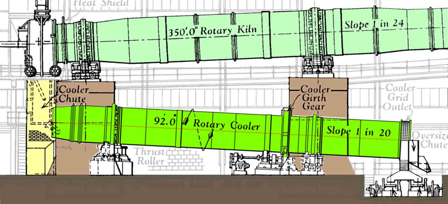 The largest British rotary cooler, by Vickers Armstrong as installed at Kent and Shoreham, 92' long and 9' in diameter. The design necessitated tall and massive kiln piers, but was easy to maintain and run.
Rotary coolers were installed on the vast majority of kilns in the first quarter of the twentieth century. They were installed either beneath the firing floor, as in the original Hurry & Seaman designs installed by Fellner & Ziegler, or beneath the kiln. The latter design had the advantage that floor space required for the kiln system could be reduced, but meant that the cooler had to pass through one or more of the kiln piers, requiring a more elaborate design of the latter.
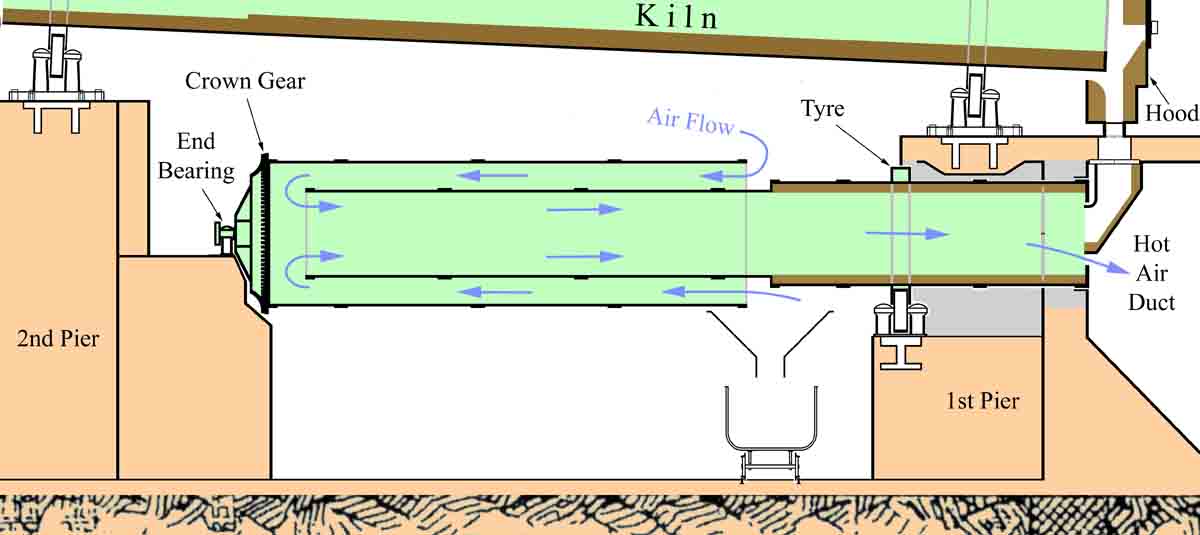 Concentric rotary cooler layout based on those at Johnsons.
One way of shortening the cooler so that the second kiln pier need not be pierced was the "double-back" or "concentric" cooler, produced by several manufacturers in the period 1905-1920. The later versions were frequently supplied with pressurisation air. Being very difficult to maintain, most of them were soon abandoned in favour of more conventional designs. The standard design coolers shown above were installed at Kent in 1949 to replace the original (1922) concentric coolers. On some smaller kilns, such as Wouldham 7 & 8, the concentric coolers were simply removed, and the kilns run with no cooling at all.
A tentative list of the concentric cooler installations is as follows:
| Kiln | Date | Supplier | Replaced |
|---|---|---|---|
| Johnsons 1-3 | 1907 | FLS | no |
| Newhaven | 1907 | FLS | no |
| Premier | 1908 | FLS | no |
| Harefield | 1909 | FLS | no |
| Wouldham 7-9 | 1910-12 | FLS | ?1929 |
| Peters 1&2 | 1911-13 | FLS | no |
| West Kent 4 | 1911 | FLS | no |
| Rugby 1&2 | 1911-13 | Newell | ? |
| ?Warren 3 | 1914 | Newell | ? |
| West Thurrock 1&2 | 1912-14 | FLS | ? |
| Wilmington 3&4 | 1913-20 | FLS | 1933? |
| Penarth | 1914 | FLS | 1933 |
| Coltness 1 | 1914 | Pfeiffer | no |
| Magheramorne 1&2 | 1914-21 | FLS | 1949 |
| ?Kirton Lindsey 1&2 | 1920-22 | FLS | ?1949 |
| Kent 1&2 | 1922 | FLS | 1949 |
From 1923, rotary coolers started to lose ground to planetary coolers, and from 1937 to grate coolers. The number of installations declined, although this to some extent reflects reduction in kiln installations, while size of coolers increased. The largest installed (Newells 89'6"×9'0¾") were among the last, on Kent A1 and A2 and Shoreham C1 and C2 in 1949-1950. The last installed was on the anachronistic Kirton Lindsey A5 in 1968.
| Date | Installed |
|---|---|
| 1900-1909 | 93 |
| 1910-1919 | 39 |
| 1920-1929 | 37 |
| 1930-1939 | 14 |
| 1940-1949 | 1 |
| 1950-1959 | 7 |
| 1960-1969 | 3 |
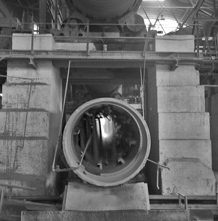 Picture: ©NERC : British Geological Survey Cat. No. P538713. This is a view (early 1960s?) into the outlet of Barrington A1 rotary cooler. Clinker cascades through the stream of cold air being drawn in by the kiln overhead. Because the cooler "lifters" are fairly worn, the hot clinker can be seen falling into the cooler at the far end. Water is being squirted in, to aid the cooling action, at the expense of cooling and diluting the secondary air.