
The essential characteristic of a grate cooler is a layer of clinker spread on a more-or-less horizontal perforated grate, through which cold air is blown. The grate is made of steel, and the cold air keeps it sufficiently cool to avoid melting or burning. The clinker progresses through the cooler by moving more-or-less horizontally along the grate, and so the direction of the cooling air is roughly at right angles to the direction of movement of the clinker, and the cooler functions as a cross-current heat exchanger. This mechanism is inherently less efficient than a counter-current heat exchanger such as a rotary or planetary cooler, but there are distinct advantages:
- the hot clinker at the inlet is treated with cold air rather than partially heated air, so that a rapid quenching effect is possible, improving clinker quality by preserving reactive high-temperature silicate polymorphs.
- by using air in excess of that needed for combustion, the clinker can readily be cooled below 200°C.
- it is easy to tap off exhaust hot air streams in desired temperature ranges for use in other processes - e.g. calciner tertiary air or drying air for fuel or raw materials.
It is fascinating to read the Fuller cooler patent of 1937: in distinct contrast to discussions of modern coolers, the preamble of the patent focuses almost exclusively on the benefits of the cooler to clinker quality.
The types of grate cooler are differentiated according to the method whereby the clinker is moved along the grate, and are treated in chronological order of their introduction.
/Cp(clinker)")

Grate coolers exchange heat between clinker and air, and because heat losses are comparatively slight, the thermodynamics of the process is simple enough. The specific heat of air is often assumed as an approximation to be equal to that of clinker, although this is not quite true, as shown.
This relates to a typical modern clinker, including the effect of the melting endotherm, and to moist air. For a narrow cross-current heat exchanger with no heat losses fed with clinker at 1300°C, the temperatures of clinker and secondary air are:
Reference to the data sheets on fuels shows that the air needed for combustion is usually in the range 335-345 kg per GJ of energy, or say 380 kg allowing a 10% excess. This means that an efficient kiln consuming 3.2 GJ per tonne of clinker will only take in 1216 kg of air per tonne of clinker - i.e. the air/clinker ratio is 1.216. Using this air alone in the cooler would result in a clinker temperature of 399°C, so the extra air needed to obtain a reasonable temperature is surplus to requirements. On the other hand, a typical Thames-side wet process kiln of the 1950s, consuming 8.0 GJ/t, would use 3.04 kg of air per kg clinker, and could therefore obtain very low clinker temperatures without (theoretically) any waste air production. Grate coolers were developed in the historical context of these less efficient kilns, and so the issue of waste air was not at that time serious.
The waste air stream is another distinct disadvantage of the grate cooler design, and limited its popularity until the 1980s. Rotary and planetary coolers operate under suction and although noisy, produce little atmospheric pollution. The waste air of a grate cooler naturally contains a large amount of gritty clinker dust. The early coolers, like the kilns, made little effort to trap this, and produced a lot of fall-out in the immediate vicinity. Furthermore, clinker dust is much more objectionable that kiln dust (which is largely unchanged raw material) because of its ability to permanently coat surfaces with hard hydration products. As environmental pressure grew, increasingly elaborate dust filters had to be fitted to grate cooler exhausts, greatly increasing the installation costs.
Bucket Grate Coolers

The first form of grate cooler used on British kilns was the Bucket Grate. The cooler was built into a greatly-enlarged kiln hood, with length about 1.9 times the kiln diameter, and width 15% greater than the length. A concave grate-plate occupied the entire base, with a pressurisation chamber below. The nose of the kiln was surrounded with a steel cylinder about 1.3 times the diameter of the kiln, on the outside of which were attached various implements, rotating with the kiln, designed to distribute and agitate the clinker on the grate, and to move it uphill towards the outlet of the cooler. A more-or-less thin layer of undisturbed clinker protected the grate from direct contact with hot material. The air-gap between the cooler shell and the kiln nose, open to ambient air, prevented these from overheating.
Nine of these coolers were installed during the flurry of kiln construction in the late 1930s, patents having been obtained in 1934. By the time kiln construction resumed after WWII, the superiority of reciprocating grate coolers had become obvious, and no more bucket grates were installed. As far as I know, the chronological order of installations was:
| 1935 | Rodmell A1 (retrofit) | removed 1957 |
| 1936 | Ribblesdale A1 (new kiln) | shut down 1982 |
| 1937 | Southam A4 (new kiln) | shut down 1979 |
| 1937 | Metropolitan A3 (new kiln) | shut down 1970 |
| 1937 | Ribblesdale A2 (new kiln) | shut down 1983 |
| 1937 | Pitstone A1 (new kiln) | shut down 1979 |
| 1938 | Southam A5 (new kiln) | shut down 1979 |
| 1938 | Rochester A3 (new kiln) | shut down 1980 |
| 1938 | Cliffe B1 (new kiln) | shut down 1969 |
The cooler at Rodmell replaced the original Edgar Allen reflex planetary cooler, and was in turn replaced in 1957 with a Fuller 633S reciprocating grate.
The buckets and paddles were very susceptible to wear, and the dead material lying on the grate surface tended to blind it. This at least meant that the hood could not be pressurised, and little dirty air passed out to the stack, but inevitably heat transfer efficiency was poor, and even with much heat-loss by radiation, clinker outlet temperature was typically 300-350°C, although the grate loading for the listed kilns was only 10-15 t/d per m2.
Reciprocating Grate Coolers
 Classic horizontal grate design. Plates had a working surface 1 ft square, plus 5 inches of overlap, a 2 inch lip and 0.25 inch gap between plates. The moving plates oscillated with an amplitude of around 5 inches.
Following the bucket grate of 1934, the first Reciprocating Grate was patented by Fuller in 1937, and early examples were installed in the USA. They started to be installed in the UK after the delay of WWII, and became the most common type of cooler on large kilns.
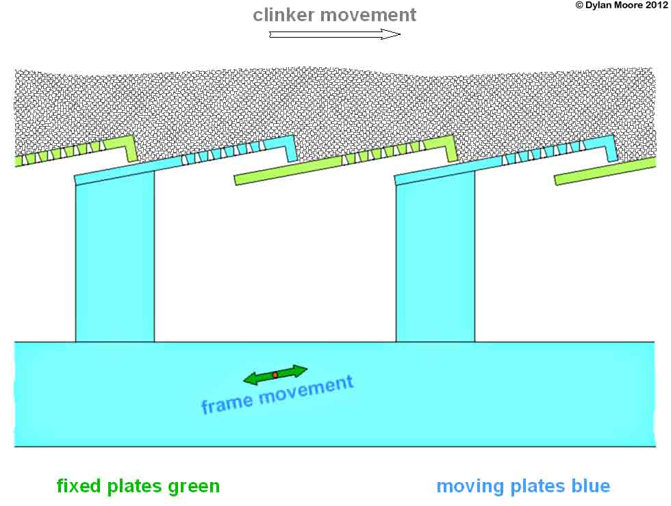
The cooler grate is composed of overlapping rows of perforated grate plates. Half of the rows are static, fixed to the casing of the cooler. The alternate rows are carried on a movable frame to which a reciprocating movement is imparted by an eccentric drive or hydraulic rams. The overlying bed of clinker is pushed forward on the forward stroke, and the plates slide beneath the bed on the return stroke. Fine clinker can fall though the grate holes, and so the under-grate chamber contains drag-chain conveyor(s) to move the spillage to the outlet end of the cooler. For most of its history, a crusher, usually in the form of a hammer mill, has been placed at the end of the cooler. Larger clinker lumps, with a low surface area, are less effectively cooled, and having been crushed, the rotary action of the hammer mill hurls the fragments back up the cooler for further cooling.
 Classic horizontal grate cooler layout.
The under‑grate chamber is generally divided into a number of compartments, each with its own fan, which can be separately pressurised. The chamber above the grate is refractory lined. Areas of cold, "dead" clinker are provided at the sides of the grate to protect those areas from over-heating. The hot air emerging from the bed passes out to the kiln, and the hot-end grate pressure is controlled to provide a small negative pressure in the kiln hood. Because, in general, more air passes through the grate than can be used by the kiln, outlet ducts are provided on the side of the cooler parts of the over-grate chamber. The hot air passing out through these may be used productively for process operations - e.g. for fuel or raw material drying - or may simply be run to waste through an exhaust stack. The hot air is inevitably heavily loaded with fine clinker grit, and so some sort of gas cleaning is provided prior to the stack.
Both sloping and horizontal grates may be used. The original design had a 12° slope. Many coolers during the 1950s had 10° slopes. In the 1960s, grates at 5° or horizontal were employed. Grates for over 1000 tonnes per day clinker output are commonly constructed in two separately-driven sections, the first (hot) part being sloped at 5° and the second horizontal. Grates over 3000 t/d commonly have one sloping and two horizontal sections. Fuller cooler sizes are designated by abbreviations, for example:
- 748S means a sloping grate 7 plates wide and 48 plates long (i.e. roughly 7 ft by 48 ft)
- 850H means a horizontal grate 8 plates wide and 50 plates long
- 825S1050H means a sloping grate 8 plates wide and 25 plates long, followed by a horizontal grate 10 plates wide and 50 plates long
Since all kilns, irrespective of process, deliver clinker at around 1300°, the size of cooler required is solely related to the expected kiln output, and grates are typically designed for a loading of 30 t/d per m2 - i.e. a kiln making 1800 t/d would require a grate area of 60 m2.
About 40 reciprocating grate coolers were installed, commencing with that on Norman C1 in 1949, which was a Fuller 620S cooler supplied under license by Vickers Armstrong. Through the 1950s and 60s both grates and planetary coolers were installed, but with the arrival of precalciners in the 1970s, needing a hot air supply that by-passes the kiln ("tertiary air"), reciprocating grate coolers became the only viable option, and subsequent developments (see below) were based upon the reciprocating grate design.
Chain Grate Coolers
The Chain Grate Cooler was developed in parallel with the Lepol preheater, and was installed on a few Lepol kiln installations. The structure of the grate is essentially that of the Lepol preheater. Secondary air and waste air are taken off in the same manner as the reciprocating grate. Unlike the reciprocating grate, the clinker remains more or less undisturbed once it has been deposited on the grate, and so efficient operation relies critically on uniform spreading of the clinker at the inlet end. The standard method, at least on early coolers, was to provide a separate, high pressure, pulsed air supply to fluidise the clinker at the inlet. The grate can't be protected by a "dead" layer and so at the inlet end it can be subject to much higher temperatures. To alleviate this, and to protect the grate from large falling lumps, on the older grates the clinker was directed onto the grate via a water-cooled steel chute. This represented a built-in heat wastage of typically 50 kJ/kg, and presented the problem of disposal of a quantity of hot water.
The chronological order of installations was:
| 1960 | Cauldon A2 | shut down 1985 |
| 1965 | Weardale A1 | shut down 2002 |
| 1965 | Weardale A2 | shut down 2002 |
| 1937 | South Ferriby A2 | extant (2012) |
Later Developments
The reciprocating grate cooler was standard for installation on modern precalciner kilns. The increasing size of the kilns and the push for minimum energy consumption led to a major reassessment of cooler design. The "modern" grate begins with the IKN patents of 1983. The essential characteristics progressively incorporated into new coolers included:
- plate air nozzles with improved aerodynamics and higher pressure drop, producing an cooling airflow less sensitive to unevenness of bed loading.
- plate designs that reduce or eliminate "fall-through" of fine clinker.
- air supply coupled directly to the plates, preventing air from bypassing parts of the grate, and allowing a more targeted application of pressure where needed.
All these are modifications of the basic reciprocating cooler design. In addition, the crossbar cooler has become available since 2000. This has a fixed grate with zero fall-through, the clinker being moved by reciprocating cross-bars above the grate surface.